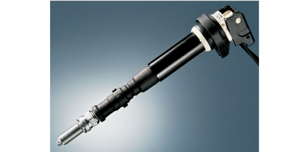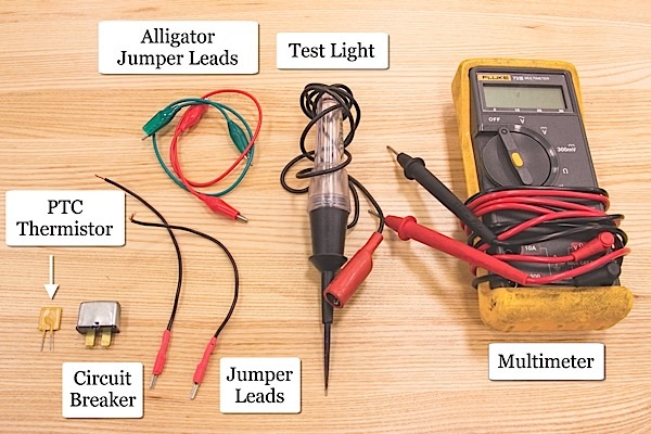
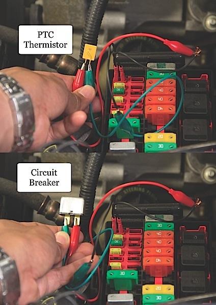
Besides the multimeter, test light and a terminal jumper lead kit, diagnosing blown fuses requires a device that can be utilized as a resettable fuse (Figure 1). A circuit breaker, similar to those found on early model vehicles, or a positive temperature coefficient thermistor (PTC), found in any electronics store, can replace the fuse during blown fuse diagnosis. It is important to choose the proper amperage rating for these devices to protect the circuit from further damage.
Similar to diagnosing other electronic problems, diagnosing blown fuses can be categorized into four main stages: verify the complaint, understand the circuit, isolate and test, fix and verify the fix. However, before jumping into diagnosis, it’s important to ask the customer about any changes made to the vehicle prior to the issue. Adding loads to an existing circuit can cause fuses or other components to fail. Another important question to bring up to the customer relates to the type of condition in which the issue occurs. One last important question to ask is if the vehicle has already been seen by another technician.
The next step is to verify the complaint. This stage requires utilizing the circuit breaker or PTC to verify the conditions that cause the fuse to fail. Additionally, a thorough visual inspection should be performed to look for exposed wiring, melted components or anything that will slow down the rotation of a motor.
Problems that occur based on temperature can be triggered with a test drive or a heat gun. A spray bottle can be utilized to simulate moisture. If the failure of the fuse is related to movement, a shake down test can be performed by slightly tugging on the wiring harnesses until the circuit breaker or PTC opens. Although these steps seem like simple diagnostic procedures, it might take a long time to find the problem without any knowledge of which circuit the fuse powers.
Understanding the circuit is very beneficial to diagnosing the problem. This second stage includes fully assessing the power distribution and wiring schematics. The power distribution schematics provide information on which system or systems the fuse is designed to protect.
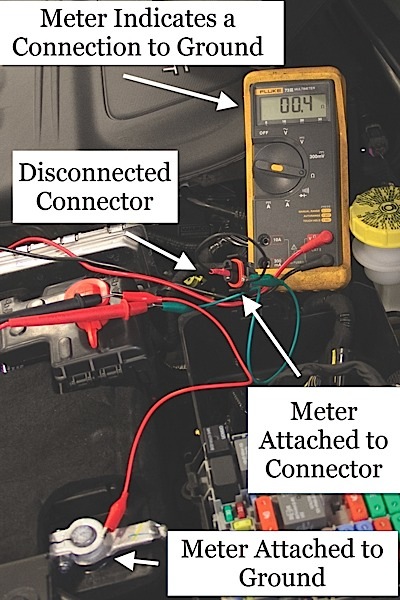
Once the problem is verified and the circuit is understood, the third stage is to isolate and test the circuit based on the information gained from the prior stages. Based on the perceived location of the problem, sections of the circuit can be isolated by disconnecting connectors, loads, switches or modules. Testing the circuit for shorts requires the use of an ohmmeter to test for continuity to ground or another wire. A quick way to test for a short to ground is to test continuity from the suspected wire to ground while the section of the circuit is disconnected from the rest of the system.
If the wire is shorted to ground, the meter will indicate a resistance lower than 1Ω (Figure 2). A similar test can be done if a wire is suspected of being shorted to another wire. It’s very important to verify that the section of the circuit being tested is isolated from the whole system. False readings may be found if not isolated.
Fixing shorts usually requires replacing a section of a wire or taping the exposed section of the wiring harness. Depending on the nature and severity of the problem, components, wiring harnesses or loads might need to be replaced. Below are two case studies to better illustrate the diagnostic procedure for issues that cause fuses to fail.
Case Study 1
The customer complains that the fuse fails when the system is turned on.
After verifying the complaint, the next step is to understand the circuit (Figure 3). Due to the fact that the issue occurs only when the switch is turned on, the problem must be after the switch. On the contrary, if the fuse failed regardless of switch position, the problem would be a short to ground on the wire between the fuse and switch. In the current situation, the fault in this circuit will be found in one of the three following areas: the wire before connector C201, the wire after C201 or at the loads. A short to ground at either wire before or after C201 will cause the fuse to fail once the switch is turned on. An internally shorted light bulb or if both wires going to a load are shorted together will also cause the same issue.
It would be best to test the resistance of the loads first. They should both be within specifications. Due to the nature of the issue at hand, a load with very low resistance will cause the fuse to fail. Once the load is verified, the problem can only be on the wires before and after C201. One way to isolate the two sections is by replacing the fuse with a test light and unplugging C201. If the test light stays illuminated when the connector is disconnected, the wire between the switch and C201 is shorted to ground. However, if the test light turns off with C201 disconnected, the problem is the wire between the connector and loads.
A continuity test from the faulty wire to ground can be performed to fully show and verify the short circuit. With the loads taken out of the circuit and C201 disconnected, there should not be any continuity to ground on the wire between C201 and the load. The last step would be to replace or repair the wire, and verify the fix.
Case Study 2
The customer complains that the vehicle intermittently dies while accelerating, going over bumps and turning left. A blown 30-amp fuse, which powers multiple circuits including the fuel pump circuit, is found to be the cause.
One of the hardest faults to diagnose are the those that seem intermittent. It’s best to first study the situation or environment that causes the fuse to fail and try to simulate the exact cause. As listed above, time, temperature, moisture and movement are some of the variables that can cause intermittent problems. Though it’s easy to see that the problem on the second case study seems to be caused by the jouncing movement of the vehicle, which would be easy to simulate, there are two other variables that need to happen. The vehicle must also be in motion while turning left.
After verifying the fault in a safe area away from other drivers, it was found that the fault would occur even while moving straight forward. This takes away the variable of turning left. This case study also illustrates the need to filter information from customers. Some will be helpful, but some can be misleading. Once the correct variables have been verified, the next step would be to understand the circuit. However, due to the intermittent characteristic of the issue at hand, it would be difficult to understand where the problem lies.
The only step left would be to isolate and test, but it would be very difficult and dangerous to diagnose a moving vehicle. The movement causing the fault in the circuit needs to be simulated while the vehicle is in the bay.
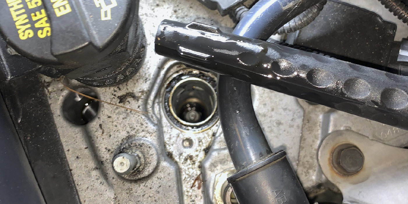
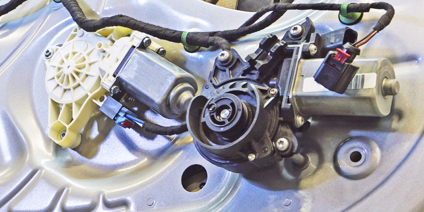
Due to the nature of the problem, performing a simple shakedown test, with the engine running, was the best way to solve the problem. A PTC or circuit breaker should be utilized in place of the fuse to indicate the high current flow. In addition, a test light can be wired after the PTC or circuit breaker to provide a visual clue of when the fuse would fail. With everything connected as shown in Figure 4, the technicians tugged lightly on the wires around the suspected area. It is best to start from the wiring harness connected to the fuse box and out to the rest of the circuits. The fault in Case Study 2 was found on a wiring harness that had rubbed against a bracket in the engine compartment. After seeing the problem, it was very apparent that the exposed wire in the wiring harness would rub against the bracket when the engine moved during hard acceleration.
Furthermore, the fault occurred over bumps when the wiring harness hit the exposed portion of the painted bracket. The problem was fixed by wrapping electrical tape around the exposed wire, replacing the damaged corrugated plastic tube, and finally by rewrapping a portion of the harness with electrical tape.
Diagnosing blown fuses can at times be frustrating, but the diagnostic steps listed above should help pinpoint the issue causing the problem. The importance of verifying the variables causing the fault and understanding the circuit can help highlight the fault. Furthermore, the two case studies detailed several issues that followed the diagnostic procedures and highlighted the steps to isolate and test the circuit. Lastly, it’s important to understand that high current is the main cause for blown fuses. Thus, the main question that should be asked is, “What is causing the increase of current flow?”