On any VW model, one or more of the following symptoms may be possible:
• Discharged battery;
• Engine does not start because of low battery voltage;
• Voltage display in the combination instrument displays too low; or
• “Low battery” fault codes in various control modules.
Production Solution:
A Battery/Current Draw Procedure was introduced in VAS 5051A/B scan tool with the release of software version 11.78.00.
Note: The power supply to the vehicle must not be cut off. Do not perform a terminal 30 reset. Do not remove or disconnect the battery, battery cables or fuses.
Checking Fault Memory:
• Compare control units on the fault memory printout with vehicle equipment (PR numbers). Are all necessary control units listed on the printout? Any control units not listed may be faulty and could be indications for further fault finding.
• Check which aftermarket parts are installed, such as a tow bar, radio, DVD, etc. If an increased closed-circuit current is found, first check these components.
Step 1—Verify Battery Condition:
1. Connect a battery charging station to the battery.
2. Check and/or charge the battery based on the applicable technical bulletin.
3. If the battery charging station test fails the battery, replace the battery before continuing.
Step 2—Verify Sleep State Current:
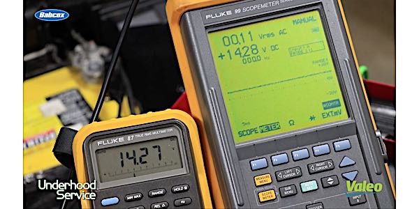
1. Connect a 50-amp current clamp to VAS 5051A/B.
2. Calibrate the current clamp.
Note: Current flows out of the battery to the chassis of the vehicle.
3. Connect the current clamp to the negative battery cable with arrow pointing away from the battery.
4. Close all doors, trunk or hood latch so the vehicle control units detect that all doors are closed.
Note: If the vehicle has easy-entry handles, then it’s necessary to keep clear of all handles to void a bus communication/wakeup message. On vehicles equipped with an air suspension, after the engine is turned off, the system will stay in standby for up to five minutes.
5. Arm the vehicle anti-theft system with the remote.
 6. Observe the sleep state current draw after the vehicle is left untouched for two hours.
7. If after two hours the vehicle exceeds maximum sleep state current draw, go to Step 3 — Consuming Circuit Isolation.
If the vehicle does not exceed maximum sleep state current draw, perform a long-term (overnight) measurement test. Record the long-term measurement using the MIN/MAX setting of the scan tool.
Note: Periodic spikes in current draw are normal.
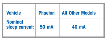
• Excessive current = Measured current > nominal sleep current.
Note: Due to the state of the CAN Bus communications in the vehicle, it’s no longer acceptable to pull each individual fuse one at a time to try and identify which circuit is consuming current. Removal/reinsertion of a fuse while the vehicle is in a sleep state may wake the bus of the vehicle and invalidate the test.
Step 3 — Consuming Circuit Isolation:
Starting at interior fuse boxes, perform the following tasks:
• Use the “mV” scale on the meter.
• Measure voltage drop across the fuse by placing the positive lead on one side of the fuse and the negative lead on other side.
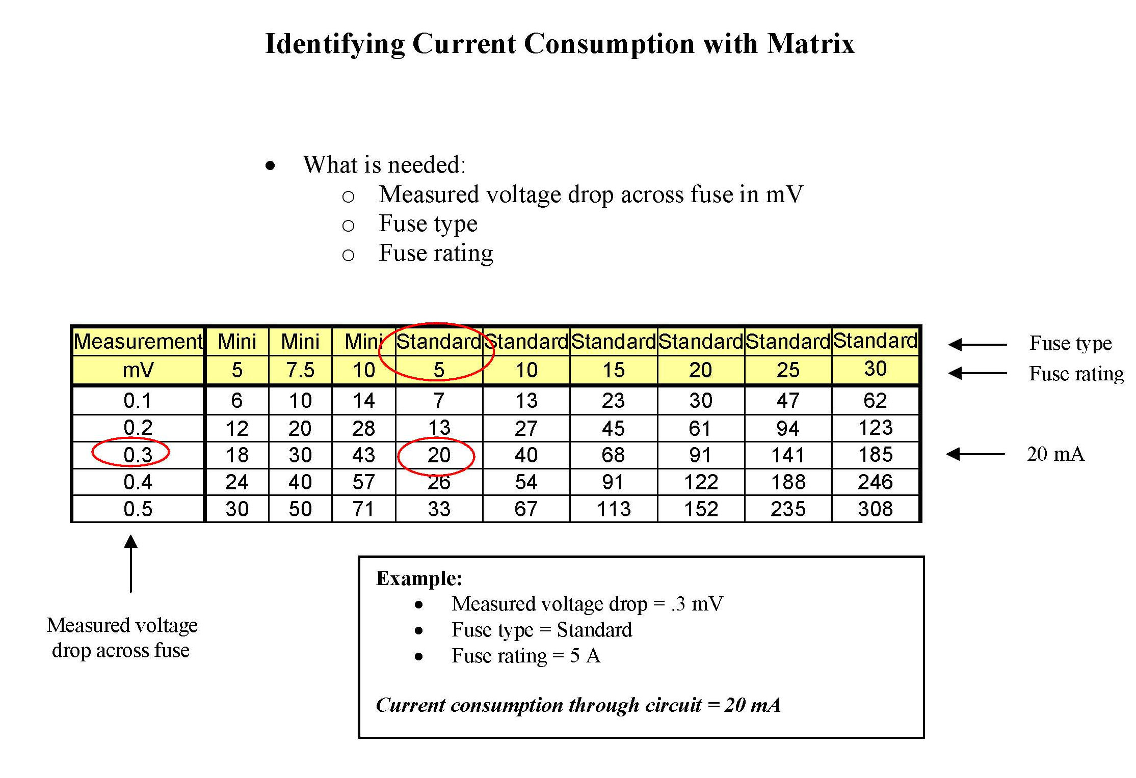
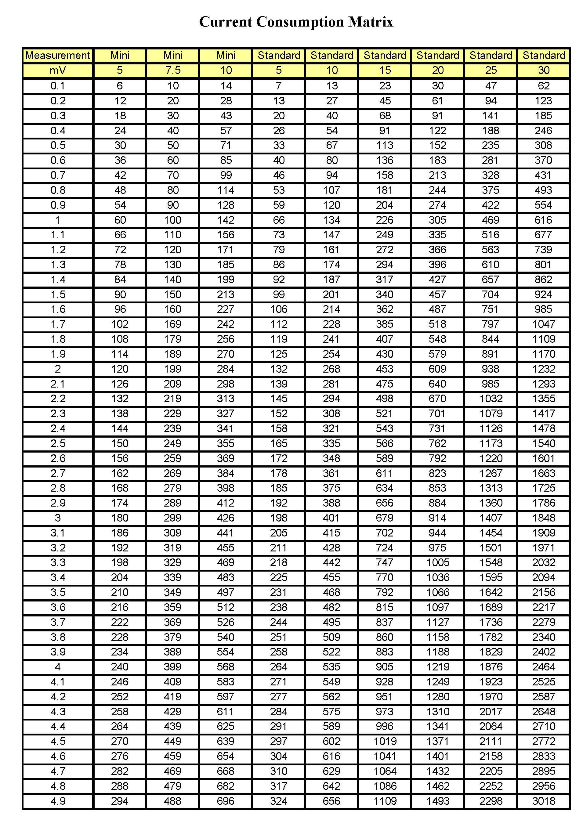
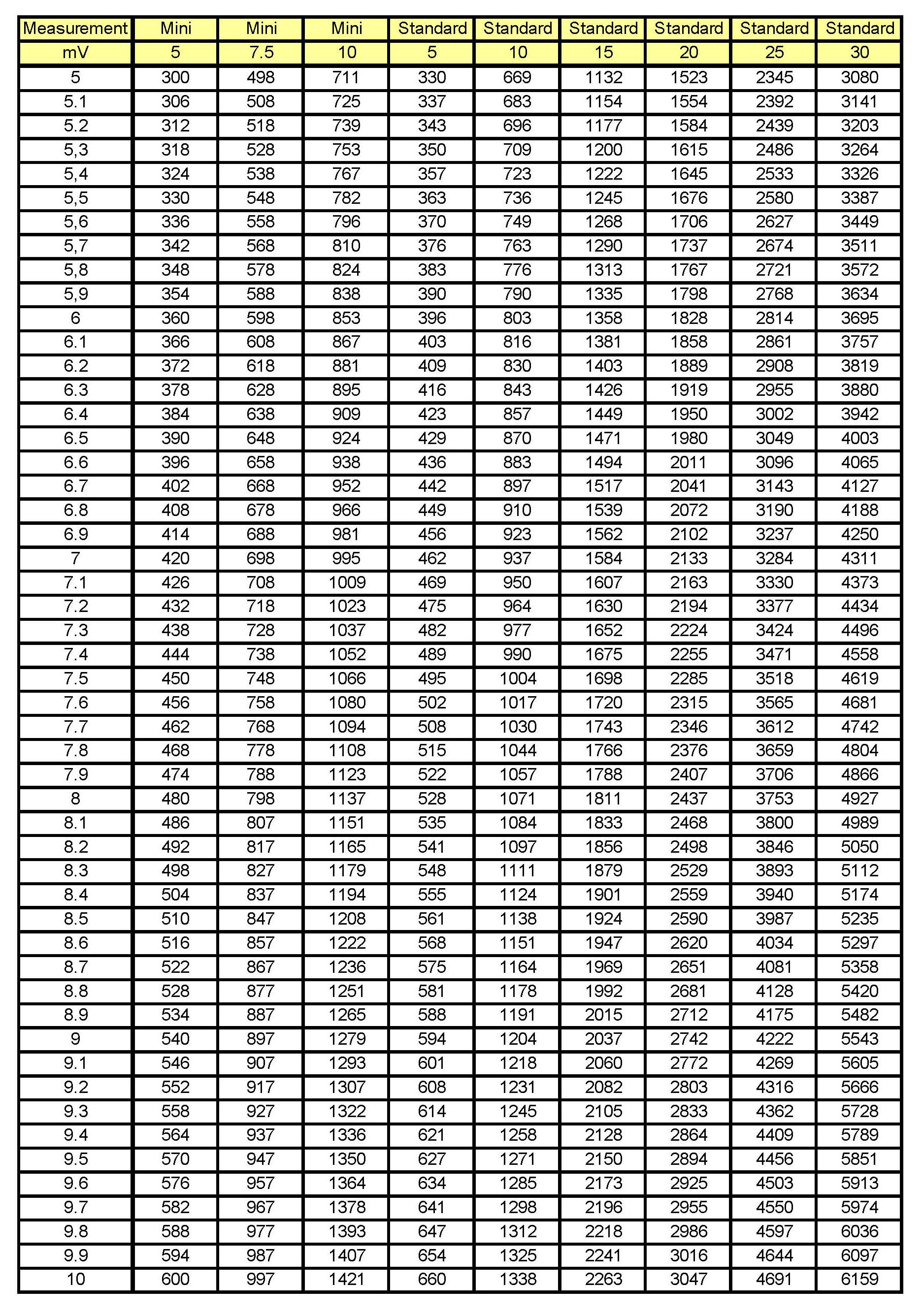
• Take the absolute value of the reading of a voltage drop (ignore negative signs) and then reference the voltage drop chart to determine how much current the circuit is currently consuming.
• Check all fuses until the fuse with the approximate excessive current draw is identified.
Identification of Component:
1. Once the fused circuit is identified, use the service repair and wiring diagram information to identify all components on the circuit.
2. Disconnect components from the circuit one by one and allow the sleep current to stabilize after each elimination.
3. Measure the vehicle’s current consumption and voltage drop across the fuse once again. If they’re within normal range, the component with the excessive consumption is identified.
4. Repeat the above steps until the component causing excessive current draw is identified.
Courtesy of ALLDATA.