This month’s Diagnostic Dilemma concerns a 2003 Chevrolet Tahoe with a parasitic battery drain that leaves it with a dead battery. The first step in diagnosing a parasitic drain is interviewing the customer to determine the average number of days and the driving conditions under which the battery drains. According to the owner, the Tahoe had to be parked approximately 10 days before the battery would no longer crank the engine.
DOING THE MATH
The second step in diagnosing a parasitic drain is understanding that most automotive starter batteries are rated at approximately 60 amp-hours, which means that the battery can discharge one amp for 60 hours until the battery reaches a terminal voltage of 10.5 volts. In the Tahoe’s case:
• 240 hours (10 days x 24 hours) is required to discharge a 60 amp/hour battery in a good state-of-health (SOH) and good state-of-charge (SOC).
• When 60 amp/hours is divided by 240 hours, the result is a .250 amp parasitic drain, which is usually equivalent to an illuminated #194 bulb or an active on-board module.
• A 5-amp drain would suggest a stuck fuel pump relay and running fuel pump, which would drain a 60 amp-hour battery in 12 hours.
Note: I once had a glow plug module on a Ford Power Stroke diesel drawing 11 amps, which would drain its two heavy-duty batteries in about 12 hours.
OLD SCHOOL
To dispel many of the old-school myths associated with locating parasitic drains, let’s begin in the era of generators controlled by mechanical voltage regulators. Mechanical voltage regulators incorporate a voltage cut-out relay that isolates the battery from the electrical system when the ignition switch is turned off. The standard test of the day was to insert a voltmeter in series between the battery positive terminal and battery cable. Battery voltage on the voltmeter indicated that the regulator cut-out relay was stuck closed, creating a closed battery circuit.
Fast-forwarding to 1964 when alternators were popularly introduced, the old-school voltmeter test didn’t work because normal parasitic drain through the alternator’s positive and negative diodes would indicate a closed battery circuit. So, we inserted a test light in series between the battery positive terminal and cable to see if the parasitic drain was large enough to make the test light glow.
Fast-forwarding again to the early 1980s, the keep-alive and adaptive memories built into the early engine computers generated enough parasitic drain to illuminate many test lights. The test light would also glow because the then-new air bag systems contained capacitors that would draw current until they were fully charged. In some cases, a test light would create enough circuit resistance to keep the air bag capacitors from becoming fully charged, and the test light would continue to glow even if a parasitic drain wasn’t present.
A favorite tactic of mine was to momentarily jumper around the test light to recharge the air bag capacitors. If the test light remained illuminated with the jumper removed, I knew I had a parasitic drain. So, I would begin pulling fuses until the test light went out. While the fuse-pulling procedure was sufficient in 1982, using that method today will cause a tech to quickly get lost in a diagnostic weed patch.

NEW-SCHOOL
CAN bus communications systems were popularly introduced into the domestic market in 2004 and were mandated as standard equipment in 2008 for all passenger and light-truck vehicles. Since the introduction of CAN, none of the old-school methods mentioned previously will locate a parasitic drain. To be brief, and perhaps at the expense of some technical accuracy in this short space, I’ll explain why.
As more accessories were added to vehicles, the size of the wiring harness bundles began to exceed the limits of practicality. By the early 1990s, engineers began reducing the size of the wiring bundles by using modules to control mechanical functions such as raising windows and activating door locks. Typically, a twisted pair of bus communications wires, a B+ power source wire, a B- ground, and a power wire connected to an accessory motor are all that’s needed to lower a window. When the “down” button is pressed on the window switch, a digital voltage signal is sent to the body control module (BCM) which, via its bus communications system, commands the door module to lower the window. The module lowers the window by activating the window regulator motor. Similar modules are now used throughout the vehicle to control the HVAC system, air bags, anti-lock brakes, power seats, fuel pumps, and other accessories.
Obviously, the battery can’t supply enough amperage to keep all of these modules “awake” 24 hours per day. To address that issue, engineers design a “master” module to command a “sleep” mode when a module is no longer needed. Most of these modules “time-out” or “go to sleep” within two hours.
When the vehicle owner or an intruder touches an exterior door handle, it awakens the vehicle security module. On more modern vehicles, any number of systems are awakened by the driver merely approaching his vehicle with his vehicle identification fob in his pocket. When the ignition is turned on, all of the on-board modules are awakened and begin performing their assigned functions. For the purpose of locating parasitic drains, suffice it to say that when a fuse is removed and replaced, or when a door is opened and closed, one or more modules are re-awakened and will remain so until they are “timed out” or “put to sleep” by the master module.
BASIC DIAGNOSTIC TECHNIQUES
The third step in diagnosing parasitic drains is establishing a stable voltage source. In brief, a battery in a good SOH won’t be fully charged until it attains a peak charging voltage of at least 14.2 volts at room temperature and the charging amperage drops below 5 amps. Using a battery charger to boost a dead battery can skew a parasitic drain diagnosis by introducing voltage variations into the battery circuit. The only exception to this rule is using a “clear” battery charger designed to maintain a very stable battery voltage for reprogramming modules.
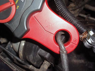
When doing mobile diagnostics, I ask that the vehicle be parked overnight with the hood up, the underhood light disabled, the driver and passenger windows rolled down, and the ignition key left on the front seat. This allows parasitic drain to be measured without opening hoods and doors. In the case of the Wide-Awake Tahoe, I measured my anticipated parasitic drain of about .240 amps or 240 mA through the battery-positive cable leading to the underhood fuse box. This proved to be an extremely valuable clue. Parasitic drains can also be similarly located by measuring at the negative battery cable grounded to the engine and at the body ground cable connected to the fender.
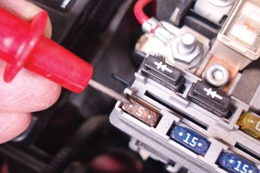
One new-school method that’s proven very useful for locating parasitic drains is measuring the voltage drop across the fuse tabs. For this test, a professional-grade voltmeter must be used. Also, the voltmeter probes must be clean and sharp to ensure repeatability. The voltage drop is measured across each fuse. I might also add that, while charts are available to translate voltage drop numbers into amperage, ideal conditions are required to produce accurate numbers.

POWER DISTRIBUTION CHARTS
The fourth step in locating parasitic battery drains is using a power distribution chart as opposed to using a wiring schematic. I discovered minor parasitic drain activity at the 20-amp ECM-B fuse located in the underhood fuse box. Using a power distribution chart, I found that the ECM-B fuse powers the fuel pump relay, fuel pump oil pressure switch, and the vehicle control module (VCM). Since about 20 mA is required to support the VCM’s keep-alive memory, I ignored that reading.
I hate pulling fuses, but it’s impossible to do a voltage drop test on maxi fuses. Fortunately, I discovered that pulling the 50-amp maxi fuse #7 would kill the parasitic drain. After consulting my power distribution chart, I found that maxi fuse #7 ultimately powers the instrument panel (I/P) fuse box. At this point, I found a rather large voltage drop across the I/P #7 auxiliary power fuse, which powers the front, console and rear auxiliary power outlets, not to mention pin #16 on the Data Link Connector (DLC).
Another interesting aspect of the Wide-Awake Tahoe case study was the 240 mA parasitic drain occasionally disappearing, which I correlated with opening the driver’s door. This indicated to me that an aftermarket anti-theft device might be causing the Tahoe’s parasitic drain. Another disconcerting aspect was that the amperage level often appeared to pulsate on my voltmeter. Connecting a low-amp probe to my lab scope and attaching a fuse loop to #7 I/P fuse, I discovered that the 240 mA parasitic drain was indeed pulsating, which is characteristic of some modules.
THE REST OF THE STORY
At this point, I found out the rest of the story of the Wide-Awake Tahoe from the shop owner. In addition to an aftermarket radio, the Tahoe also had an aftermarket anti-theft security system installed. Removing the radio had no effect on the parasitic drain, so the client shop had also removed an aftermarket vehicle security system. So, what was causing the drain? Exploring under the instrument panel with a bright flashlight, I found an aftermarket fuse holder with a 10-amp ATO fuse inserted. Removing the ATO fuse killed the 240 mA parasitic drain, which solved this month’s Diagnostic Dilemma.
A DIAGNOSTIC SUMMARY
Remember that professional equipment is mandatory for testing parasitic drains. In this case, I used a new self-contained inductive amp probe ranging from about 10 milliamps to 40 amps capacity. This probe “zeros” very quickly and appears to be much less affected by magnetic fields than my older inductive amp probes. That, plus my professional-grade digital volt-ohm meter (DVOM) and lab scope were all I needed to locate the troublesome parasitic drain.