A 2001 Frontier (D22) or Xterra (WD22) may exhibit one or both of the following symptoms:
- MIL “on” with DTC P1491 (Vacuum Cut Valve Bypass Valve – VC CUT/V BYPASS/V) stored in the ECM; and/or
- Difficulty refueling the vehicle.
The vehicle’s fuel tank may need to be replaced. Use the appropriate Service Procedure provided in this bulletin to diagnose and repair these incidents, if they should occur.
Service Procedure:
Warning: Before performing any of the Service Procedures below, be certain there are no ignition sources (i.e., open flames, sparks, etc.) in or around the vehicle/work area. Make sure the appropriate rated fire extinguisher is available for immediate use.
MIL “On” With DTC P1491 Stored:
1. Connect CONSULT-II.
2. Turn the ignition key to “on” but do not start the engine.
3. Select “ENGINE,” “DATA MONITOR,” “EVAP SYSTEM PRESSURE SENSOR.”
4. The pressure sensor value should read between 3.32 and 3.40 volts (3.36 volts is the nominal value):
- If the value is between 3.32 and 3.40 volts, proceed to step 5 below.
- If the value is not between 3.32 and 3.40 volts, refer to the EC Section of the vehicle-specific service manual for diagnosis of DTC P0450 (EVAP System Pressure Sensor) to repair the vehicle.
5. Start the engine and allow it to idle.
6. Monitor the EVAP Pressure Sensor value with the engine idling:
- If the EVAP System Pressure Sensor value decreases more than 0.02 volts from the reading shown in step 4, the EVAP Purge Volume Control Solenoid Valve (in the engine room) is leaking engine vacuum (not sealing). Replace the EVAP Purge Volume Control Solenoid Valve.
- If the EVAP System Pressure Sensor value decreases less than 0.02 volts from the reading shown in step 4, or does not change at all, replace the fuel tank and O-ring.
Note: Refer to the vehicle-specific service manual, Section FE (Fuel And Exhaust)/Fuel System/Removal And Installation/Fuel Tank for detailed instructions on fuel tank removal and installation. Follow all warnings and cautions provided in the service manual.
Difficulty Refueling the Vehicle:
1. Use a suitable device to remove the fuel from the fuel tank.
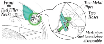 2. Check that the two metal pipes attached to the Fuel Filler Neck are clear (See Fig. 1).
Notes:
- Mark the pipes and hoses before disassembly. Use duct tape and an indelible marker (See Fig. 1). This is so they can be correctly identified for reassembly. If the hoses are later reconnected incorrectly, refueling difficulties may occur.
- One of the pipes has a restrictor inside of it and will flow slightly less than the other, however, they should both be clear (not blocked).
- The pipe with the restrictor is connected to the lower of the two nipples on the fuel tank. This is the signal line. The upper nipple is connected to the filler neck pipe without a restrictor in it. This is the recirculation line.
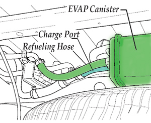 3. Remove the large diameter refueling hose that attaches onto the charge port of the EVAP canister (see Fig. 2).
4. Try to refuel the vehicle:
- If the vehicle is no longer difficult to refuel, check the EVAP canister and water separator and hoses for restrictions/debris and repair/replace as needed.
- If the vehicle is still difficult to refuel, replace the fuel tank and O-ring.
Caution: Remember to reattach the hose disconnected in step 3.
Note: Refer to the vehicle-specific service manual, Section FE (Fuel And Exhaust)/Fuel/System/Removal and Installation/Fuel Tank for detailed instructions on fuel tank removal and installation. Follow all warnings and cautions provided in the service manual.
Technical service bulletin courtesy of Mitchell 1.
For additional information, visit www.mitchell1.com.