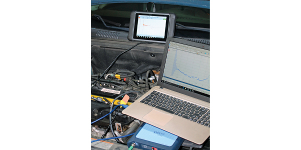
The grandfather of all waveforms is the secondary ignition waveform. Technicians have been looking at this waveform since the 1960s to determine the health of ignition system components. The secret to being able to capture and analyze secondary ignition waveforms is understanding what is happening in the coil and at the spark plug and how the scope measures and graphs the voltages and ignition event.
How Is It Measured?
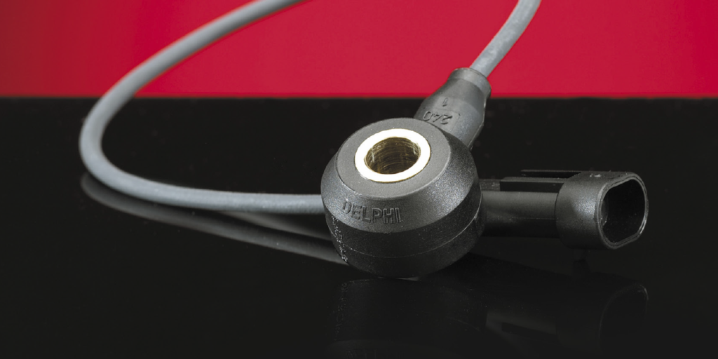
Measuring the voltage of the secondary ignition directly is not an option – these high voltages will damage any scope or meter. Capturing a secondary ignition waveform requires a capacitive probe. This type of probe can be either the traditional clamp over an ignition wire or a “paddle” that makes contact with the surface of the coil or wire.
The primary and secondary windings of the coil transform the energy from low-voltage/high-current energy to high-voltage/low current energy. Eventually this energy is discharged through the spark plug electrodes. The flow of energy changes the magnetic field in the wires or coil and this change in the field is picked up in millivolts by the clamp or paddle probe.
Most clamp or paddle probes have a conversion factor of 10:1. This means one volt at the scope input equals 1,000 volts or one kilovolt (kV) in the secondary. Some clamps or probes may have an attenuator (10:1 or 20:1), so make sure you read the instructions to properly set up your scope. Some scopes will convert the voltage scale to kV when the ignition probe is selected.
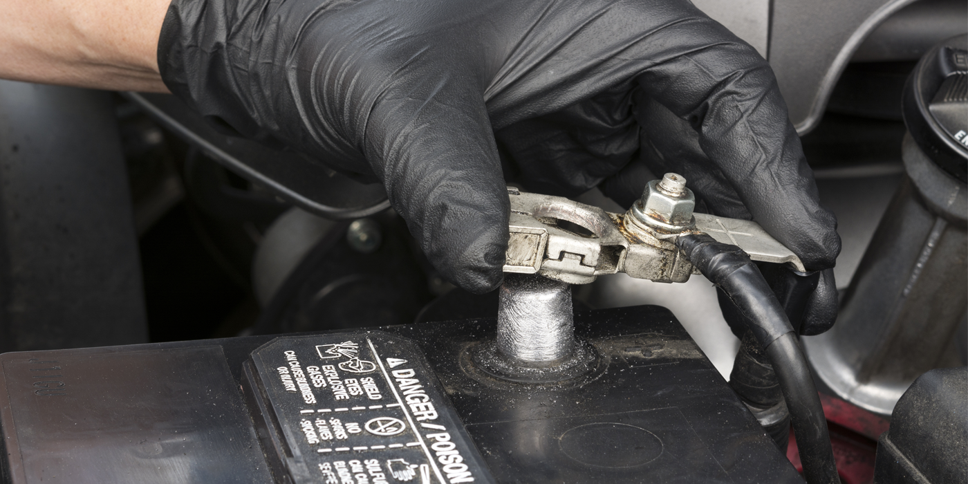
A capacitive probe should include a ground clamp as part of the test leads. This creates an easier path to ground for the thousands of volts generated by the coil. If the probe or clamp is not grounded, the voltage could damage the internal circuitry of the scope. Most scopes have a limit around 200 volts, and most ignition systems can generate more than 4,000 volts.
What Are The Settings For The Scope?
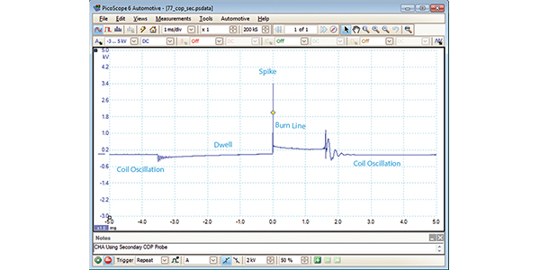
When you are trying to set up a scope to measure secondary ignition waveforms, the goal is to capture the ignition event from when power is applied to the coil to the point where the coil oscillates with the remaining energy. This can happen in 6-10 milliseconds. One millisecond per division is typically the optimal time base depending on the size of your screen and the type of ignition system.
A healthy coil and ignition system generates 5-7 kV at idle. As load and engine speed increase, the kV spike will increase. Some systems can generate more than 50 kV under certain conditions. You may need to adjust your voltage scales to capture the total output of the spike. Don’t get caught up on the height of the spike. Automakers are actively controlling the output of the coil to improve the longevity of the ignition components.
On most scopes, the trigger should be set to auto or single with an increasing slope. With some scopes, you will be able to use an auto or repeat trigger setting to stabilize the waveform. There are also options to offset or delay the trigger to fit the entire event on one screen.
Try to become familiar with setting up secondary ignition triggers within your system before you are under the diagnostic labor gun. If you have a more advanced scope, you can select the secondary ignition probe in the probes menu – the presets will load the correct voltage range, time base and type of trigger. Some scopes will also convert the voltage scale to kV. Depending on the type of ignition system, you may have to fine tune the trigger and voltage scale to fully capture the waveform on a single screen.
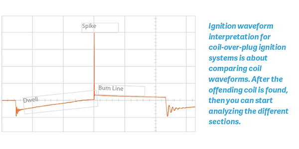
What Are The Sections Of The Waveform?
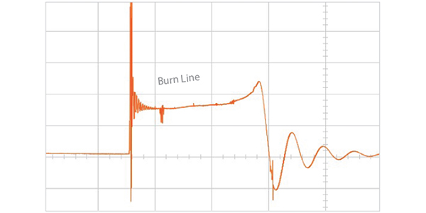
A secondary ignition waveform can be broken down into three parts. First, the area of the waveform shows dwell where the secondary of the coil is saturated with energy from the primary. Second, the spike shows the initial start of the spark between the electrodes. Third, the burn time is the area of the wave where the spark is burning between the electrodes and eventually stops.
Interpreting Secondary Ignition WaveForms
On modern coil over plug (COP), wasted spark or coil near plug systems you are using the secondary waveform as a comparative tool to compare the cylinders. You can compare a waveform to a known good pattern from a database or you can compare the waveform to the other cylinders. Waveforms will differ from engine to engine.
On some systems, you may see a 1- to 2-kV hump after the spike, or you might not see a coil oscillation when the primary coil is energized. This could be normal for some systems and abnormal for others.
The secret is to compare the waveform with the other actual cylinders. Don’t get hung up on “this guy said this” or “that book says that.” In some cases, you could go down a diagnostic black hole.