Models
2007-2009 Versa Hatchback (C11X)
2007-2009 Versa Sedan (SC11X)
Symptoms
• The MIL is “ON” with one or more of the following DTCs stored: P0442, P0448, P0455, P0456 AND
• EVAP vent control valve is stuck open or will not seal when operated/closed.
Service Procedure
NOTE: Filter kit installation procedure shown as performed on a Versa Hatchback. The procedure for Versa Sedan is similar.
1. Remove the rear bumper fascia. Refer to the appropriate ESM as needed.
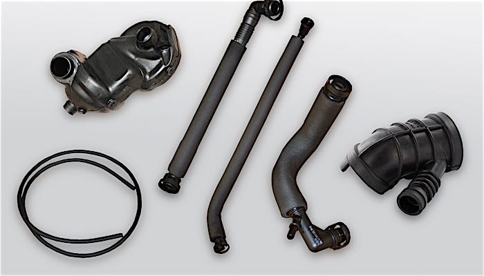
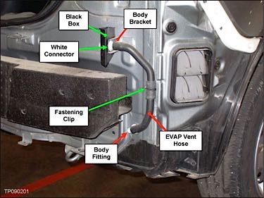
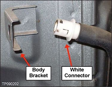
2. Remove the existing hoses, black box and white connector from the vehicle (see Figure 1).
a. Remove the black box from the white connector and then the white connector from the body bracket (see Figure 2).
NOTE: Save the white connector. It will be reused. The black box will not be reused.
CAUTION: Be careful not to bend the body bracket.
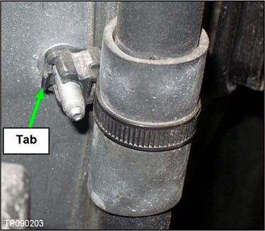
b. Remove the hose and its fastening clip from the body stud.
Pry back on the clip’s tab and then pull it off (see Figure 3).
3. Drill two 7/32 inch (5 mm) holes in the bracket (see Figure 4).
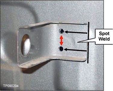
Drill the holes about 1 inch (25 mm) from the edge of the bracket (black arrows), with about 3/4 inch (19 mm) spacing in between (red arrow in Figure 4).
NOTE: Measurements are taken from the center of the holes.
Do not drill any part of the spot weld. Adjust the drilled hole location(s) as needed.
NOTE: The bracket and/or its spot weld may not be in the exact same location when compared to other like vehicles. This is normal.
4. Prep the holes you just drilled as follows:
a. Remove burrs from the edge with a file or sandpaper.
b. Clean the hole with solvent and allow to completely dry.
c. Apply / cover all bare metal with zinc-rich primer.
d. Allow primer to dry approximately 1 hour.
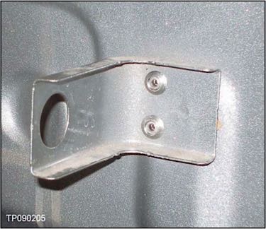
5. Using a suitable pop rivet tool, install the two sealed-type blind rivets supplied in the filter kit (see Figure 5).
NOTE: Do not use any rivets other than the ones in the kit.
6. Coat / spray the rivets and the area around them with bitumen wax.
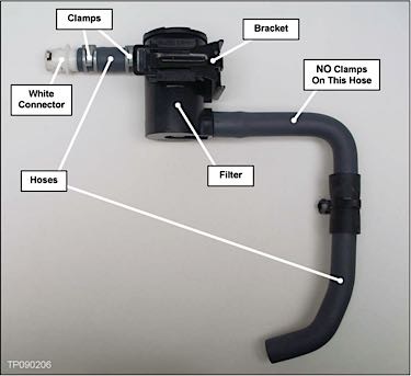
7. Assemble the two hoses, existing white connector, filter and bracket (see Figure 6).
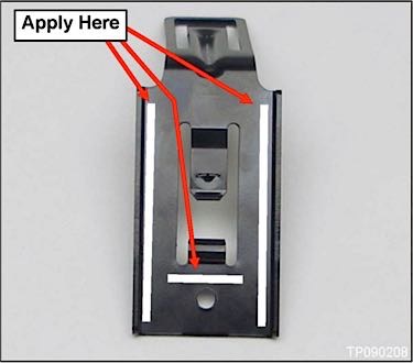
8. Apply a thin layer of liquid gasket about 1/8 inch (3 mm) wide to the areas shown with white lines (as specified in Figure 7).
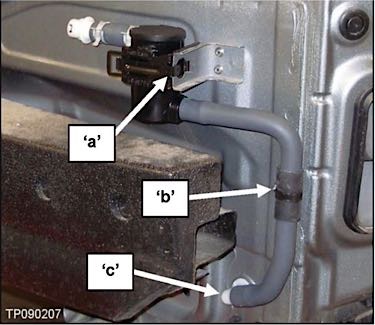
9. Snap in place the filter bracket to the body bracket (see “a” in Figure 8).
10. Secure the hose clip by pushing it onto the body stud until it bottoms out (see “b” in Figure 8).
11. Connect the hose to the body fitting (see “c” in Figure 8).
12. Reinstall the bumper fascia. Refer to the ESM for installation procedure as needed.
13. Clear any DTCs stored in the ECM.
Courtesy of ALLDATA