In 2010, GM announced that most LS V8 engines would be equipped with variable valve timing (VVT). Before this, VVT had already been available on GM’s small-block 6.0L and 6.2L V8s. GM did not ditch the pushrods and the camshaft in the block for the new model. Instead, they put a very sophisticated actuator on the end of the camshaft.
The CMP actuator system controls the amount of intake and exhaust valve overlap. The engine control module (ECM) can only command the CMP actuator to advance the valve timing from the park position or retard the valve timing back to the park position.
Oil Pressure Management
The camshaft has an internal oil passage that carries pressurized oil to the CMP actuator. Pressurized engine oil enters the camshaft at the second bearing journal oil galley.
The oil from the camshaft travels through a check valve and then a filter. The check valve keeps oil in the system after the engine is turned off. The oil then enters a spool valve that controls the flow to the CMP vanes in the actuator. Oil exits the valve and travels within the internal passages of the camshaft into the entry ports of the actuator.
The spool valve’s position is controlled by magnets and the ECM. When the spool is moved to the proper position, oil flow is directed through the valve and into the CMP actuator assembly. The CMP solenoid valve is a torque-to-yield design and should be replaced each time it is removed.
CMP Actuator Control
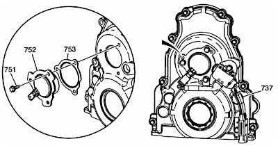
The CMP actuator magnet is located in the engine front cover and is sealed by a press-in-place gasket. The CMP actuator magnet is controlled by a 12-volt 150 Hz pulse width 0-100 percent duty-cycle signal from the ECM. When energized, the solenoid uses electromagnetic force on the magnet pintle to position the spool valve of the CMP solenoid valve.
The CMP actuator is a vane-type design that hydraulically changes angle or timing of the camshaft relative to crankshaft position. The CMP actuator allows earlier or later intake and exhaust valve opening. The CMP actuator cannot vary the duration of valve opening or valve lift. The CMP actuator is to be serviced as an assembly.

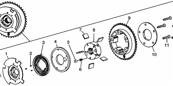
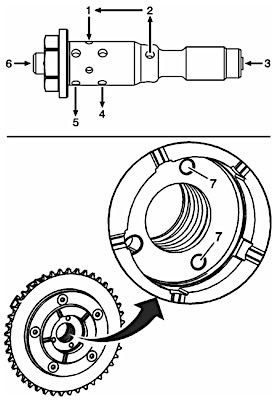
The CMP actuator consists of:
- reluctor wheel #1
- wheel retaining pins #2
- return spring #3
- front cover #4
- park position pin #5
- park position pin spring #6
- vanes and vane springs #7
- rotor #8
- housing/chain sprocket #9
- thrust plate #10
Do not push or pull on the reluctor wheel of the CMP actuator during removal or installation. The reluctor wheel is retained to the front of the CMP actuator by three roll pins. Pushing or pulling on the wheel may dislodge the wheel from the front of the actuator. The actuator return spring is under tension and may rotate the dislodged reluctor wheel, causing personal injury.
CMP System Operation
A CMP actuator dynamically changes valve timing events relative to piston timing by controlling camshaft position. This is sometimes referred to as variable valve timing or camshaft phasing.
There are five cavities divided by vanes within the CMP actuator. When oil is directed to the advance cavities, the camshaft timing is advanced. When oil is directed to the retard cavities, the camshaft timing is retarded. When oil is directed to both cavities, the camshaft is held stationary.
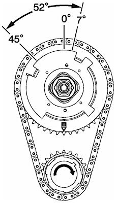
The CMP actuator has a 52 degree range of movement at the camshaft (later models have 62 degree range of movement). With the engine not running and no engine oil pressure to the CMP actuator, the high-tension spring positions camshaft timing at the 7 degree advanced park position at the crankshaft (3.5 degrees at the camshaft).
During normal engine operation, and based on performance requirements, the ECM may adjust camshaft timing as required within a range from 7 degrees advanced at the crankshaft (3.5 degrees at the camshaft) to 55 degrees retard at the crankshaft (27.5 degrees at the camshaft).
CMP System Lubrication Flow and Actuator Operation
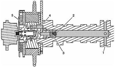
- Oil enters the camshaft at the second main bearing journal #1.
- Oil travels through the camshaft into the CMP actuator valve check ball #2 and filter #3.
- Oil exits the valve and travels through the internal passages of the camshaft #4.
- Oil exits the camshaft and enters the actuator oil entry ports.
- Oil travels through the actuator and is directed back into the valve #5.
- Valve spool position directs oil to the advance or retard passages of the actuator.
The valve may also, under certain conditions, be positioned in a neutral position with alternating low, balanced oil flow between the advance and retard passages of the actuator.
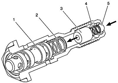
Oil flows from the camshaft into the valve inlet #3 through the internal check ball and filter.
Oil exits the valve #2 and travels within the internal passages of the camshaft into the entry ports #7 of the actuator.
The center oil groove of the actuator is pressurized and oil reenters the valve #1.
Valve spool position directs oil out of the valve advance #5 or retard #4 ports to the actuator.
The valve may also, under certain conditions, be positioned in a neutral position with alternating low, balanced oil flow between the advance and retard passages of the actuator.
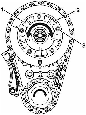
- Pressurized oil enters the retard cavities #2 of the actuator and moves the park pin #3 from the locked position.
- As pressure increases within the retard cavities #2, the rotor and camshaft rotate counterclockwise, retarding valve timing.
- As the duty cycle decreases, the spool is repositioned and oil is sent to the advance cavities #1, rotating the rotor and camshaft clockwise, advancing valve timing.
- With a 0% duty cycle signal to the magnet, the spool is positioned in the fully extended position and there is full flow to the advance cavities of the actuator. As duty cycle increases to near 50%, flow to the advance cavities is decreased.
- With a 50% duty cycle, the spool is positioned neutral with no flow to either the advance and retard cavities.
- With a 51-100% duty cycle, the spool is positioned to provide oil flow to retard cavities. As the duty cycle increases, the flow to retard cavities increases.
- With a 100% duty cycle, there is full flow to the retard cavities of the actuator.
- The above duty cycle percentage values are only a guideline, as the actual duty cycle values may vary based on engine oil temperature, solenoid magnet coil temperature, magnet coil resistance and other specifics.