If you drove a vehicle from the late 1990s with traction control, you might recall the systems were not that smooth. Most of these systems cut spark or fuel instead of changing the angle of the throttle. These systems could not change the throttle angle because it was connected to a cable. Throttle-by-wire changed that.
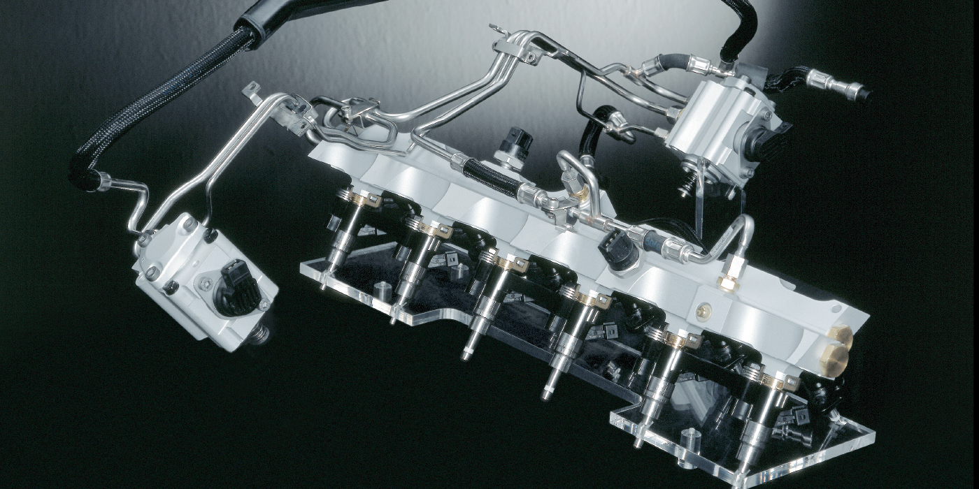
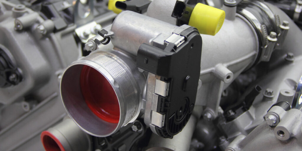
An electronic throttle body is very similar to the cable-operated throttle body, with a few notable changes. Among the most noticeable is the addition of the throttle actuator control motor. This motor is used to open and close the throttle plate based on direct commands from the engine control module.
The motor turns two reduction gears inside the throttle body that link the drive gear from the motor to the throttle plate shaft. On most systems, idle speed is entirely controlled by the throttle plate angle. Gone are the idle air control motors, idle stabilizers and tiny drilled holes in the throttle plate.

Throttle-by-wire creates harmony between the throttle angle, ignition and fuel, which allows the engine to generate more torque and power. Throttle-by-wire can also better utilize variable valve timing and direct injection by matching the right amount of air with the fuel.
The throttle position sensor (TPS) has been redesigned for the throttle-by-wire. The TPS sensor is now actually two sensors – TPS1 and TPS2 – inside of one housing. TPS1 is viewed by the engine control module as the primary source for throttle plate position under normal conditions. TPS1 behaves in the reverse of a traditional TPS (it has a negative slope). In the at-rest position, the voltage is near the 5-volt reference voltage. As the throttle plate opens, the voltage from TPS1 lowers.
TPS2 is used to crosscheck TPS1. TPS2 is also used by the system for small throttle angle changes because it has better resolution than TPS1. In the event TPS1 fails, TPS2 becomes the computer’s primary source of throttle plate position. The voltage from TPS2 behaves in the traditional TPS manner. In the at-rest position, the voltage is less than 1 volt and rises toward reference voltage as the throttle plate opens.
TPS1 and TPS2 do not mimic each other in voltage value. As you can see, the slope angle of TPS2 is about twice that of TPS1. TPS1 provides a signal that covers the entire sweep, which is similar to older versions of TPS on cable-operated systems. The only real difference is the negative slope of TPS1. TPS2, however, reaches its peak voltage twice as fast. The voltage slopes change at different rates to further isolate TPS1 from TPS2 in the eyes of the engine control module. The connector for the throttle body module will be pins for the two TPSs, ground, reference/signal voltage and two wires for the motor that connect to the engine control module.

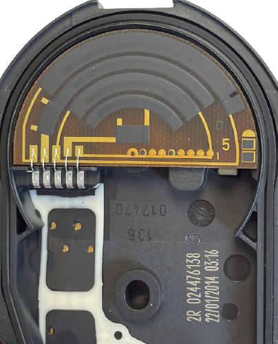
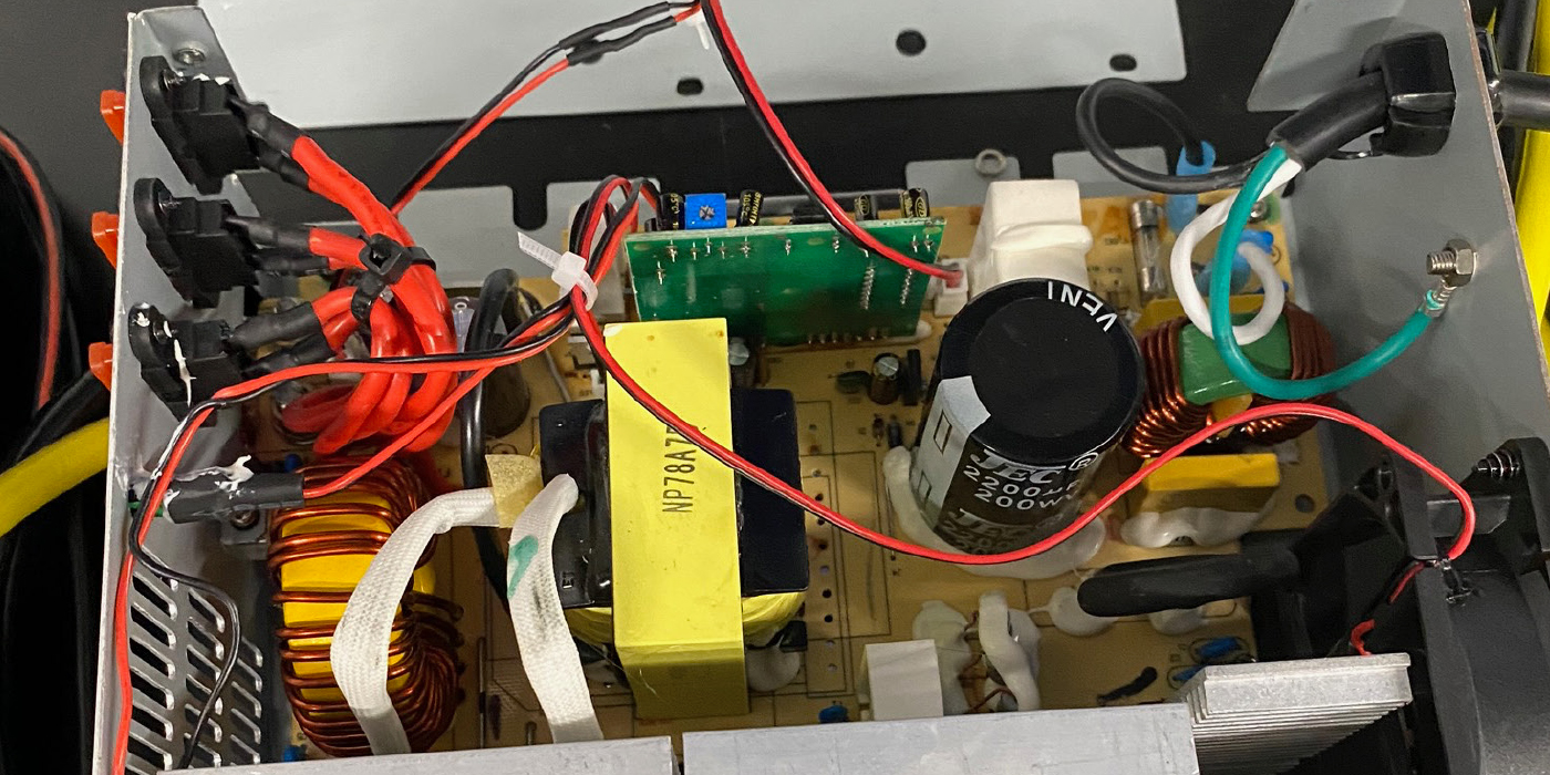
On some late-model systems, the TPS out will not be accessible to test in the connector. New throttle-by-wire systems have the TPS sent to a module on the side of the unit. The data from the sensors is then shared over a data bus with the engine control module. GM uses a simple UART bus to connect to the throttle body module. The module on the throttle body will also be connected to the cruise control system and a brake pedal position sensor input that can be provided by a switch or shared with the ABS control module.
Throttle-by-wire systems are designed to operate without service for many thousands of miles. Part of this trouble-free operation is the design of the area around the throttle plate. Some manufacturers use a coating around the bore where the plate operates. This Teflon-like substance prevents the buildup of carbon, oil and debris.
Some manufacturers recommend cleaning the surface with just a shop rag with no or minimal solvents. GM recommends cleaning with solvents that do not contain methyl ethyl ketone (MEK) in the ingredients. MEK can harm coated surfaces and damage the bushings and seals around the shaft of the plate. There are throttle-body-specific cleaners available that are formulated so they will not damage the majority of throttle bodies on the market.
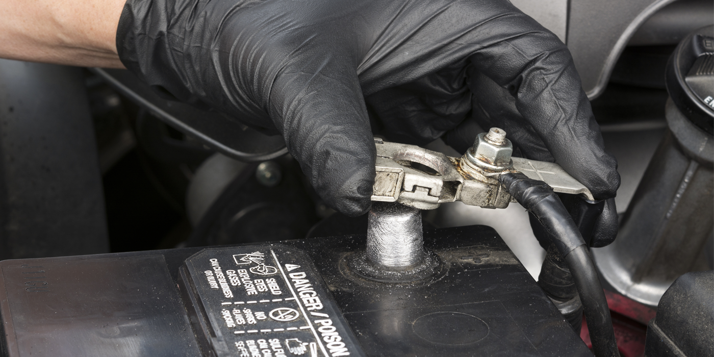
Once the throttle-by-wire unit is cleaned and installed, the vehicle will have to relearn the values of the pedal and plate. Some vehicles do this automatically every time they are started. Some vehicles require a unique key, pedal sequence and battery disconnect, while others even require a scan tool to relearn the positions.
Swapping one throttle-by-wire unit for a new unit in hopes of resolving a code or limp-mode problem is not an option due to the high price and strict manufacturer return policies. Instead, being able to think through and diagnose a throttle-by-wire problem is critical to working on late-model vehicles.
The most crucial diagnostic tip with throttle-by-wire is to consider the other inputs and outputs. Controlling the throttle angle can make for a smoother shift in the transmission. Throttle angle can also be controlled so when an A/C compressor clutch engages, the driver will not notice. If there are missing inputs or data, the throttle-by-wire system might not function as intended.