Since fuel trim technology might sound like black-box magic to many working technicians, let’s break away from the science of fuel trims for a moment and concentrate instead on the day-to-day aspects of interpreting them.
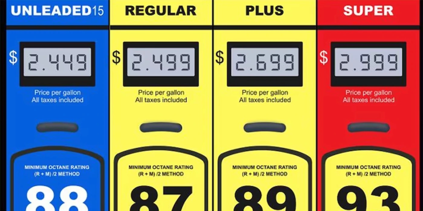
If we’re on the leading edge, we know that air/fuel ratios can range from 13:1 to 22:1 on modern engines. But don’t hit the panic switch. No matter what the air/fuel ratio, there’s a fuel trim cell that addresses these specific air/fuel ratios (see Photo 1).
The short version of fuel trim diagnostics is pretty simple: modern feedback fuel systems rely on oxygen sensors and air/fuel ratio sensors to report the oxygen content of the exhaust stream to the ECM. We also know that the ECM’s short-term fuel trim (SFT) describes real-time data. The ECM adds or subtracts fuel by comparing the short-term oxygen content of the exhaust stream to data contained in individual cells that form the ECM’s fuel trim tables. Each cell contains a specific fuel injector pulse width that matches a specific engine operating condition.
The ECM then stores these fuel corrections in its long-term fuel trim (LFT) memory. The function of the long-term memory is to adjust fuel injector pulse width during engine start-up to correspond with barometric pressures and ambient temperatures existing at the time the engine was shut off.
We know too, that when the oxygen sensor indicates excess oxygen in the exhaust stream (which indicates a lean condition), the ECM increases fuel injector pulse width to restore exhaust oxygen levels to those specified in that cell. When the absence of oxygen in the exhaust stream indicates a rich air/fuel mixture, the ECM reduces injector pulse width to restore the desired oxygen level for that particular cell.
EXCESS OXYGEN
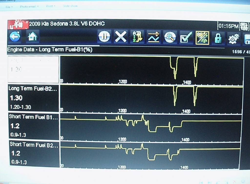
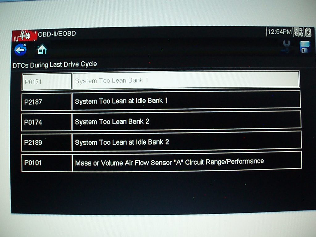
Excess oxygen in the exhaust stream sets a P0171 (bank 1 lean) or a P0174 (bank 2 lean) code. Although bank 1 (B1) and bank 2 (B2) generally refer to V-block cylinder configurations with an oxygen sensor on each bank, some in-line engines split their exhaust manifolds to create a B1 and B2, each equipped with its own oxygen sensor. Excess oxygen symptoms generally include poor cold-drivability, rough idle and perhaps a few P0300-series engine misfire codes.
EXCESS OXYGEN AT HOT IDLE
Remember that the software programmed into the ECM affects how P0171/174 is set. In general, codes P0171/174 are set when the ECM adds 25% or more fuel. As a rule of thumb, a mass air flow sensor should see one gram per second (g/s) of air flowing for each liter of engine displacement at hot idle with accessories off in a neutral gear.
If, for example, 2.0 g/s of air is flowing into a 3.0-liter engine at hot idle under no load, an air leak in the ducting between the MAF sensor and throttle body is causing the MAF to underestimate intake air flow. The ECM will subsequently reduce injector pulse width to correspond with the lesser air flow measurement. Depending upon software configuration, a P0171/174 will set.
If the engine is equipped with a speed-density system, the ECM will calculate air flow data by using data such as throttle position (TP), manifold absolute pressure (MAP), engine speed (TACH), intake air temperature (IAT) and engine coolant temperature (ECT) data to estimate air flow into the engine.
Most large vacuum leaks produce MAP sensor readings that will be slightly low and perhaps idle speeds will be slightly high. If you’re familiar with idle air control (IAC) readings, the IAC count or the IAC duty-cycle percentages will be less than normal because the ECM is trying close the idle air control (IAC) valve to reduce idle speed.
In any case, if the 25% positive fuel trim returns to nearly zero as the engine speeds up, it’s certain that the P0171/174 is caused by an air leak that shows up only at idle speeds. In most cases, an air or vacuum leak can be quickly located by using a metered source of alternative fuel like propane to add fuel. Using due diligence for flammable materials, I couple a 12-pound propane bottle with a pressure regulator, a precision metering valve, vacuum hose and metal wand to quickly locate the sources of air leaks into the intake system.
Last, let’s not forget that air leaks into the exhaust stream can mimic an intake manifold leak and set codes P0171/174. In short, the oxygen sensor is “sniffing” excess oxygen and delivering a false “lean” signal to the ECM. The easiest way of diagnosing exhaust leaks is to partially block the exhaust outlet with a shop rag to create a positive pressure in the exhaust. If fuel trims immediately return to less than 10%, you’ve found your problem.
EXCESS OXYGEN AT SPEED
In short, we’re probably looking at a marginally failing fuel pump or fuel filter that isn’t delivering enough fuel to the engine at speed. In this case, the ECM can no longer increase injector pulse width enough to compensate for the lack of fuel pressure and volume, so the P0171/174 code is set.
The first step is to locate the freeze-frame data contained in your enhanced scan tool. Some scanners contain freeze-frame data in their “global” menus while others contain that data in their enhanced menus. No matter the location, freeze-frame data describes the exact operating conditions under which the P0171/174 was set. If either or both codes set only at highway speeds, you’re probably looking at a fuel delivery problem.
EXCESS FUEL AT IDLE
Excess fuel in the exhaust stream will set P0172/175 codes in the ECM’s diagnostic memory. Physical symptoms will be sooty spark plugs and sooty tail pipes; performance characteristics will be good cold-engine drivability and sluggish warm-engine performance. In some instances, a P0300-series misfire code might be caused by fouled spark plugs.
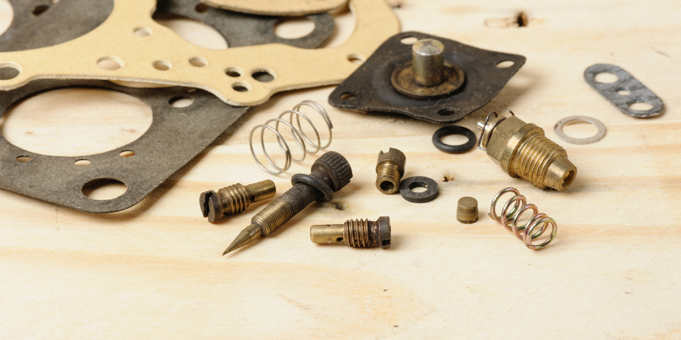
Before we begin taking things apart, let’s look at the possible sources of excess fuel. Begin by checking for the presence of fuel in the engine oil caused by excessive short trip driving in cold weather. Next, a leaking fuel pressure regulator diaphragm is always a prime suspect on early dual-line fuel systems. To diagnose, check for the presence of fuel in the vacuum modulation hose attached to the pressure regulator. Negative fuel trims at low engine speeds are always good indicators of leaking fuel pressure regulators.
On all dual-line fuel systems, always test for fuel excess fuel pressure caused by a stuck-closed fuel pressure regulator or a crimped fuel pressure return hose to the fuel tank. In short, the ECM can’t sufficiently reduce injector pulse width enough to establish fuel control.
STUCK-OPEN INJECTORS
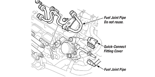
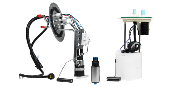
Modern single-line fuel pumps have placed fuel pressure regulation inside the fuel tank, which leaves fuel injectors as a likely source for fuel leakage into the intake manifold. Due to various intake manifold configurations, a leaking fuel injector might not easily set a P0172/175 code. Instead, look for -25% or higher negative fuel trims on one bank.
Due to high negative fuel trims, a leaking fuel injector will reduce average fuel injector pulse widths from about 2-3 milliseconds (ms) to 1.0 ms or lower to correct for a hot-idle, excess fuel condition. The next step is to locate the faulty fuel injector by removing the spark plugs. The spark plug with the most soot indicates the cylinder with the faulty injector.
CLOGGED INJECTORS
In this case, we’re looking at P0171/174 codes and high percentages of positive fuel trims, usually for one bank. Assuming we’ve eliminated air and vacuum leaks as a cause, we’re looking at a clogged fuel injector. In most cases, positive fuel trims will be found on the cylinder bank with the clogged fuel injector. Due to an air/fuel mixture that’s too lean, that cylinder might also produce a P0300-series misfire code. Looking at the misfire histories in your scan tool, the cylinder with the highest misfire count is likely to contain the clogged fuel injector.