Gasp! It’s the “Gas Cap Code”!
Oh no, you just pulled a code P0422, evaporative purge small leak detected… Here goes the needle in the haystack syndrome.
So what do you do? Recommend a new gas cap and ship it? Well you could do that, but would that be in your or your customer’s best interest? You might get lucky and fix some like that. However, that type of approach is a recheck waiting to happen. With very strong communication skills up front, you may get away with it with that customer that day, but what about when the car comes back? Then what? The car still has to be fixed. What’s worse is that the customer will likely return on a busy day and mention in the lobby in front of other people how they had to come back.
That’s not good publicity for your other customers to overhear, since they don’t fully understand the reasons for that customer coming back. So, wouldn’t it be better to have fixed the car on the first visit? Obviously, yes. So, let’s cover basic evaporative emissions system theory and operation. Afterward, we will look at a couple of evaporative emissions system problems and diagnose them. Technically specific information found in this article will be based on Ford vehicles. However, much of this information also can be applied to other makes. Always consult your repair information resources for vehicle-specific information.
Theory and Operation
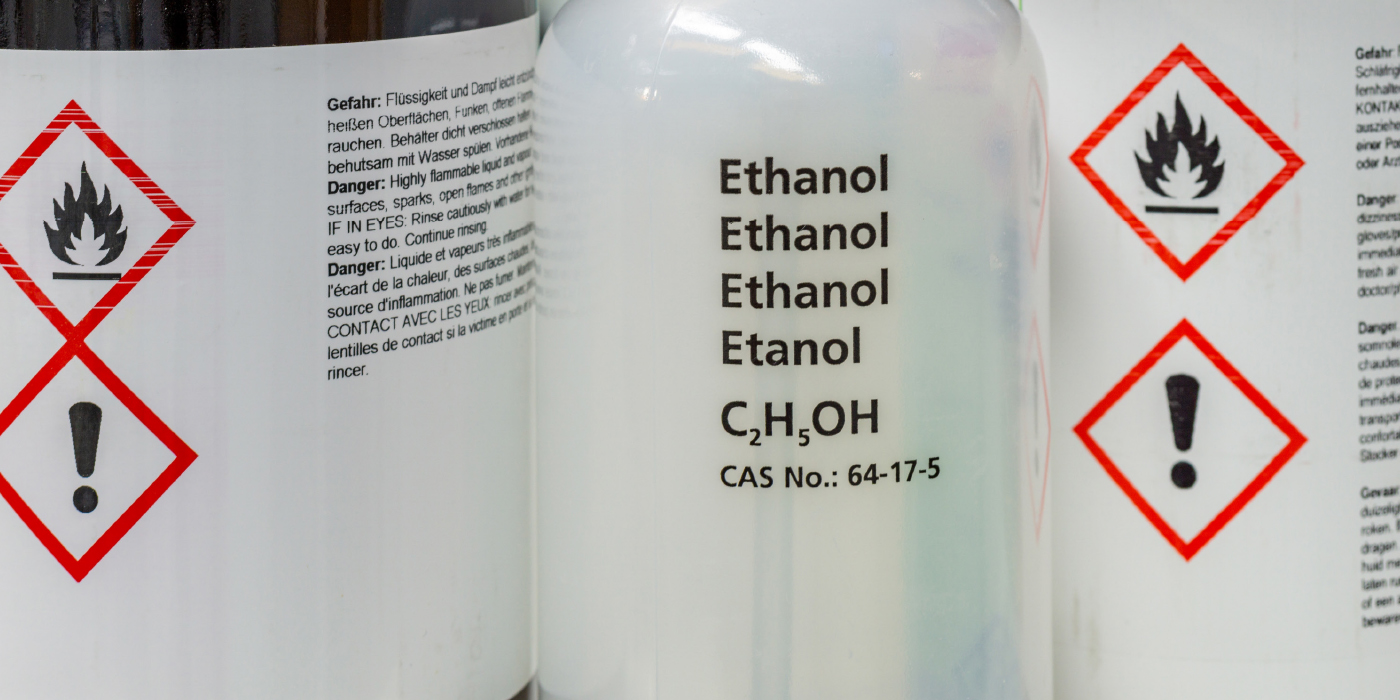
Due to the volatile nature of gasoline, vapors are generated in the gas tank. It’s important that these vapors are not just vented into the atmosphere for more than one reason. First and foremost is that these fuel vapors are hydrocarbon emissions. Releasing them will promote smog. Another important reason, is that these fuel vapors are the flammable part of the gasoline that would power the engine. Releasing them to the atmosphere would be the equivalent of leaking raw fuel out of a gas tank. I think we can all agree that with the price of gasoline today, no one would want to do such a thing. So, we would want to make sure the evaporative emissions system is properly functioning to take full advantage of those vapors.
There are two main types of evaporative systems: enhanced and non-enhanced. Non-enhanced systems are found on OBD I vehicles. Some of the OBD II vehicles that were built during that “funny” period in 1994 and 1995 (when manufacturers produced OBD II vehicles that were not fully OBD II compliant since it was not federally mandated at that point) also may have non-enhanced evap systems. Truly OBD II-compliant vehicles have enhanced evap systems.
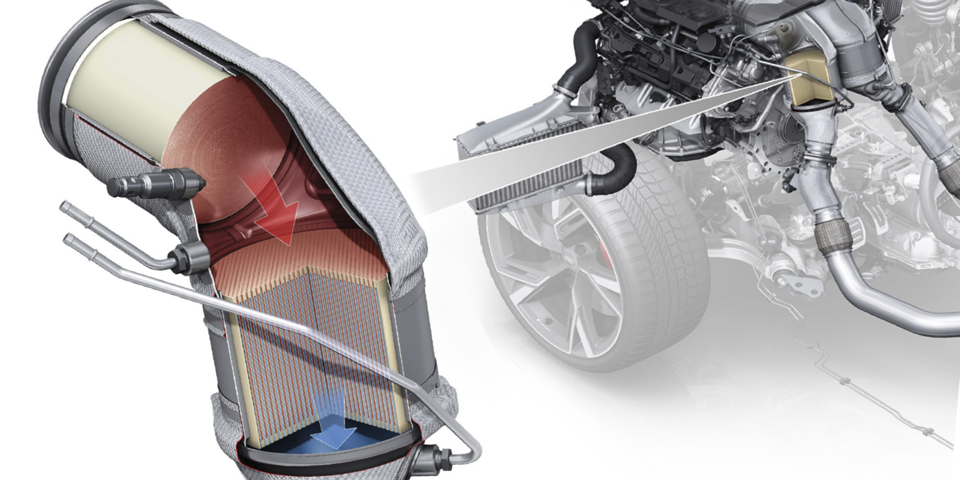
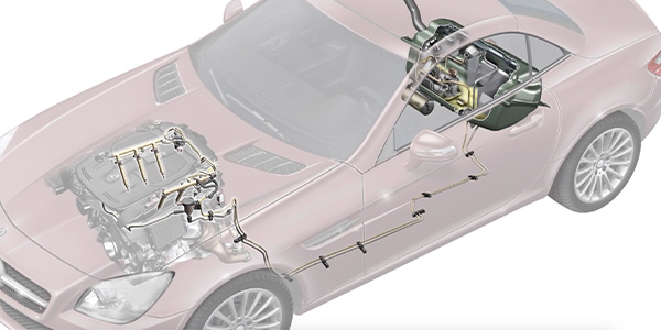
With both systems, fuel vapors from the gas tank are routed to the intake manifold on the engine. A charcoal canister is plumbed in parallel to the intake manifold, and is used to store fuel vapors until the appropriate time that they can be burned. The charcoal canister also provides an escape path for fuel vapors in the gas tank during refueling. Some systems only purge above idle and some systems purge nearly all times during closed-loop operation, depending on individual system type and PCM strategies. A rollover valve prevents liquid gasoline from leaking through the purge lines and canister when the tank is over-full, and in the event of a vehicle rollover. The fuel cap has a two-way valve inside of it that will vent tank pressures over 14 kPa (2.03 psi) and relieve a vacuum below 3.8 kPa (1.122 Hg).
Non-Enhanced Evap Systems
The non-enhanced evap system is a flow-monitoring system (without acknowledgement to the even older completely extinct non-enhanced evap technology that is). This system uses a purge valve and flow sensor, or a vapor management valve. A single vapor management valve is a replacement for a purge valve and flow sensor combination.
This system cannot detect leaks. It can, however, determine whether or not anything is flowing when the purge solenoid has been commanded open. The system in
Figure 1 uses a flow sensor to determine when the system is flowing. Typically, these systems do not purge at idle. The newer non-enhanced evap systems replaced the purge solenoid and flow sensor for a vapor management valve (VMV). See Figure 2. The VMV can more accurately meter the purge flow than the purge solenoid. The PCM monitors the vapor purge volume based off of feedback from the O2 sensor. Evap systems with a VMV also can purge at idle. The PCM makes the decision when to purge at idle and when not to purge at idle, based on IAC correction.
Enhanced Evap Systems
The enhanced vapor management system has all of the components as the non-enhanced VMV system. The enhanced system adds to that a fuel tank pressure sensor, test port, a fuel level signal to the PCM, and a canister vent solenoid. See Figure 3.
This is a leak monitoring system and is OBD II compliant. Normally, the canister vent solenoid is in the “venting” position. The PCM grounds the vent solenoid to seal off the system during leak testing. While not leak-testing, the vent solenoid is open. This includes key off, engine off so that air trapped in the tank can be vented out during refueling.
Evap System Monitor
There are two parts to the evap system monitor’s leak test: a “gross leak” test and a “small leak” test. The small leak check is further broken down into leaks greater than 0.040” (1.016 mm) in size and leaks greater than 0.020” (0.508 mm) in size. Not all vehicles that you encounter will check for leaks down to 0.020” (0.508 mm) in size.
Before the monitor can run, some criteria must be met. First of all, the O2 monitor must have first run with no faults set. The engine must be off for at least six hours. The test will start to run at least 330 seconds from start, but not longer than 1,800 seconds from start. Intake air temperature has to be between 40° F and 100° F (4° C and 38°C). Barometric pressure has to be above 22.5 inches of mercury (in. Hg.) (0.7619 Bar and 11.05 psi). Engine load has to be at a steady rate somewhere between 20% and 70% load. Vehicle speed also must remain steady between 40 mph and 75 mph. The purge duty cycle has to be between 75% and 100%. The fuel tank pressure sensor must be reading between -17” of water (-0.6141 psi) and 2.5” of water (3.556 psi).
The first to run is the “gross leak test.” For this test, all of the above criteria must be met, plus there cannot be less than 15% fuel in the tank, nor can there be more than 85% fuel in the tank. This can be viewed on an OE scan tool and some aftermarket tools. See Figure 4.
The PCM starts by closing the vent solenoid to seal off the tank, canister and lines. The gross leak test is simple. The PCM is simply “looking” to see if it can draw the tank down to a target vacuum. When viewed on a scan tool, the event may look like Figure 5.
If the target vacuum cannot be achieved, then the test is aborted and a code is set for “gross leak detected” (P0455, P0457, P1443 or P1450). Of course, this will be a “pending code” — it will have to fail the same test again to be a fault code and turn on the MIL light. Some newer model vehicles have a “gas cap” light. This light is illuminated if, before the leak is detected, the PCM also detects a 20% or more gain in fuel level at key-on cycle compared to the level at the last time the key was turned off.
If the PCM is able to draw the tank down to the target vacuum, it then begins the “small leak” checks. It continues to hold the vacuum, and monitor how long it takes for the vacuum to bleed up. On a scan tool it may look like Figure 6.
If the vacuum bleeds up past a threshold limit (the threshold in the screen shot is 1.84 volts on the FTP sensor) within 20 seconds, a leak larger than 0.40” has been detected. If this happens, the PCM will repeat the test two more times for a total of three leak tests. If the test fails all three times then the PCM enters a “vapor generation test.”
For the vapor generation test, the PCM opens the vent solenoid to neutralize the pressure in the tank. See Figure 7.
After a stabilization period, the PCM once again closes the vent solenoid. This time, the PCM commands 0% duty cycle at the VMV. Both ends of the system are now sealed. The PCM now watches the fuel tank pressure sensor for rise in pressure. Any rise in pressure is looked upon by the PCM as the fuel turning to vapor. See Figure 8.
If the rise in vapor pressure doesn’t exceed a threshold voltage on the fuel tank pressure sensor, then the PCM has verified a leak. The PCM will now set a pending code for leak detected (P0442), and will mature that pending code into a fault code with an MIL light the next time the same test fails. However, if the fuel tank pressure sensor voltage rises too far during the vapor generation test then a leak has not been verified. If that happens, then the PCM has no choice but to start over with the entire leak-testing process from the beginning without setting a code.
If the test for a 0.040” leak passes, some vehicles will continue the testing to look for leaks down to 0.020”. The criteria to run the 0.020” test can be tricky. It can run at idle or at cruise depending on the conditions that the vehicle is subjected to when the PCM is ready to run the test. Normally, it will run at idle. After it passes the 0.040” test, then there must between 50% fuel and 85% fuel in the tank. The ambient temps must be between 40° F and 80° F. The PCM, during normal driving, will then draw the tank down into a vacuum (-7 H2O) in anticipation of a chance to perform the 0.020” leak test at the next idle or speeds under 3 mph. However, if the PCM has a refuel event flagged after the 0.040” test passed, or the vehicle has not had an idle event within 10 minutes of the 0.040” test passing, then the PCM will enter a 0.020” test at cruise. The 0.020” leak test is performed the same as the 0.040” test. It is simply measuring the fuel tank pressure sensor’s input over time. The PCM just gives the tank approximately twice the amount of bleed up time as the 0.040” test. The exact amount of time for either test is dependent on the amount of fuel in the tank. If the system has determined that there is a leak as small as 0.020”, then it will set a fault code P0456 (very small leak detected).
Data collected during the evap tests can be viewed in the mode $6 data stored in the PCM’s KAM. The evap system test data in mode $6 reflects the results of the last time the test ran.See Figure 9.
Test ID 21 in Figure 9 is the result of when the PCM pulled the initial tank vacuum. Looking at the “min” and “max” specs shows that the PCM’s target vacuum is between -8” H2O and -7” H2O. The “value” shows the test result. The test value was passing.
Test ID 22 shows the amount of vacuum loss during testing. There is a limit of not more than 3” H2O leakage allowed. The test result “value” for test 22 was a passing vacuum loss of only 1” H2O. Test ID 25 is the vapor generation test. During this test, the PCM is expecting to see a rise in fuel vapor pressure more than 1” H2O. If it is below that point, then a leak would be confirmed. But why is the value -63” H2O? Did it fail? No, this was a properly operating evap system. The only problem revealed in this mode $6 shot is that #6 cylinder has been misfiring. So why the -63” H2O value? That is a default value the PCM selects until the test runs. In fact, test 21 and 22 also default to -63” H2O if the codes or KAM have been cleared. In this case, the vapor generation test has not run yet. Remember from earlier, the vapor generation test only runs if a leak is suspect. Since test 22 passed, the PCM has no reason to run test 25 so the default value is displayed.
Diagnostics
As with any system on the vehicle, it’s important to understand the direction in which the trouble codes are pointing you. Obviously, not every “evap” code set by the PCM will be pointing to a leak. Some other evaporative emissions system related codes that you might run across are: P0443: EVAP Control System Canister Purge Valve Circuit Malfunction: The PCM monitors the health of the canister purge solenoid circuit by “watching” voltage drop. This code is pointing you in the direction of either an open or shorted evap canister purge solenoid circuit.
P0451: FTP Sensor Circuit Noisy: This code means that the PCM has seen the reading from the FTP sensor fluctuate more than 14” H2O within 0.10 seconds. This code would most likely be caused by a poor connection in the circuit.
P0452: FTP Low Voltage: This code is saying that the circuit to the FTP sensor is constantly below 0.22 volts. Look for a short to ground.
P0453: FTP Sensor Voltage High: This is the opposite of a P0452. In this case, the voltage is above 4.5 volts from the FTP sensor. Look for an open circuit.
P1443: Very Small or No Purge Flow Condition: This means that the PCM has determined that the purge flow rate was less than 0.02 lbs. per minute. Look for a restriction in the purge hose, like a kink in the line or even a stuck closed purge valve. If the system uses a flow sensor, then the flow sensor could be at fault.
P1450: Unable To Bleed Up Fuel Tank Vacuum: This means that the PCM is seeing the fuel tank still in a state of vacuum after it has opened the vent solenoid. Look for a continuous source of vacuum to the tank, like a stuck open purge solenoid, or a restriction in the vent line such as a stuck closed vent solenoid or debris blocking the vent hose from the vent solenoid.
P1451: Vent Solenoid Circuit Malfunction: This means that that there is an electrical failure with the vent solenoid circuit. The circuit is either open or shorted to ground. It could even have a blown fuse.
2002 Ford Mustang
OK, so now you pull in your next check engine light complaint and find an evap leak code P0422 on an 2002 Mustang 3.8L. See Figure 10. What’s the next thing to do? Boy, that’s a loaded question, huh? Because the next step is a little different for everyone. So I’m just going to share what my next step is. My next step is simple; I’ll read into what the code is really telling me. In order to set a P0442, the purge solenoid had to be capable of purging the tank. The vent solenoid had to close and seal well enough to hold that vacuum for a few seconds. And… the gas cap was installed and at least sealed well enough to let the tank reach the target vacuum. Though nothing has been ruled out yet, the priority list of things to check is now obvious to me. After all, I’m not worried about checking fuses when I know the tank would never get into a state of vacuum at all with a blown fuse to either the vent solenoid or vapor management valve. Besides, we’d have different codes for that anyway. It’s obvious that we are looking for a leak. So let’s start looking for one.
The best tool for the job at this point is an evap-approved smoke machine. We’re going to use the machine to verify the presence of a leak. Using the scan tool, close the vent solenoid. If your scan tool can’t command the vent solenoid closed, then you will have to ground the vent solenoid manually. Using the calibrated leak detection gauge, we have verified that a leak is present.
Now we switch to smoke. Add the smoke through the test port on the evap line. This should be a green-capped fitting under the hood. If there isn’t one, then it’ll have to be added through the filler neck by a special adapter that fits in place of the gas cap. Turn on the smoke. If adding though the test port, it is helpful to remove the filler cap until the smoke appears at the filler neck and then reinstall the fuel filler cap. It also can be helpful to monitor the FTP sensor when filling the tank with smoke. See Figure 11.
Begin inspecting with a bright light when the FTP sensor has reached a peak in voltage. In this case the smoke machine peaked the FTP sensor at 3.42 volts. See Figure 12.
 Be sure to wiggle the fittings while inspecting for a leak. Remember, the PCM tested and found the leak while cruising so fittings were vibrating when the PCM was testing.
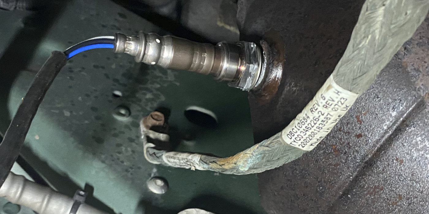
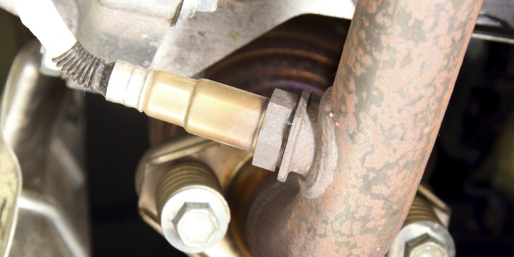
This time, the leak was found to be something fairly common to this style of Mustang. The filler neck seal at the tank was splitting and leaking. See Photo 1.
A new one fixed it right up. The difference could even be seen in the higher FTP reading while under a follow-up smoke test. The new peak voltage was 4.72 volts. See Figure 13.
The proof of the fix came from inspecting the system once again with the calibrated leak measurement gauge on the smoke machine. The ball no longer floated, proving no air leakage through the evap system. See Photo 2.
 2001 Ford F-150
The next vehicle is a 2001 F-150 with a 4.2L engine. The complaint was check engine light, rough idle and intermittent misfire. Scanning the system found an evap gross leakage code, a misfire on #3 code and a bank 1 lean code. See Figure 14.
On the surface, this appears to be three completely unrelated codes. A quick look at the fuel trims and IAC count revealed what could be a vacuum leak. Fuel trims were in the high teens at idle and IAC counts were unusually low in the teens as well. Attempting to operate the evap  purge system revealed exactly what a “gross leak” means: the PCM could not draw a vacuum. To do this, the IAC valve was first opened to raise the engine rpm. This has to be done because normally if the VMV opens at idle, the engine may stall out. The next step was to command the vent solenoid 100% closed to seal the system. Lastly, the VMV was commanded to 100% open and the FTP voltage and/or the calculated tank pressure PID were monitored. See Figure 15.
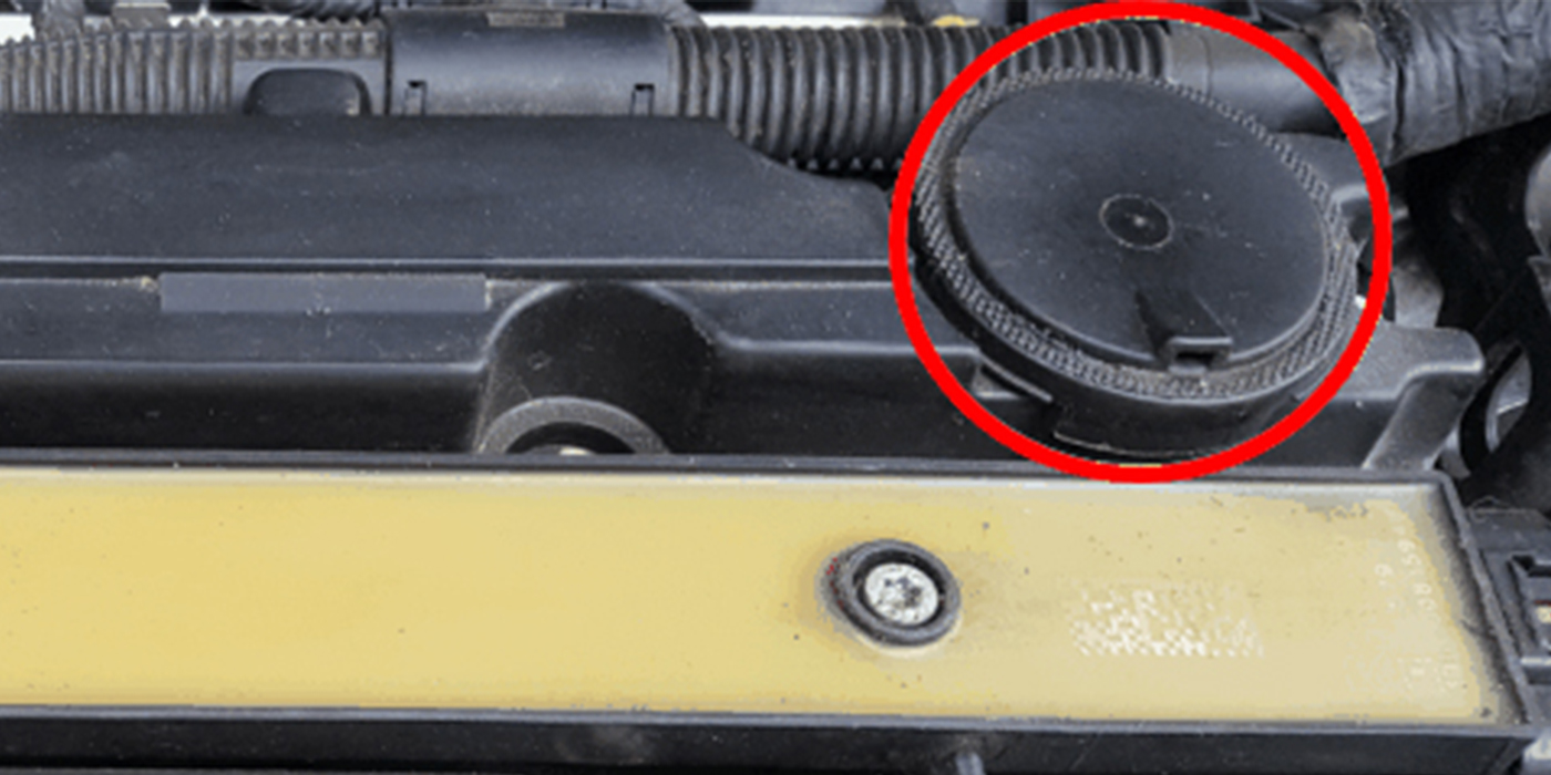
In this case, no change at all was found in the FTP readings as the VMV was opened. So we just verified a gross leak… right? Ah, no. All we verified is what the code was really telling us. Not that there is a leak, but rather that the PCM has lost the ability to draw the tank into a  vacuum for some reason. So, starting with one of the easiest possible causes to check — the gas cap — revealed a properly installed cap. So it’s on to the next easiest possible cause, the VMV. Pulling the small vacuum line at the base of the VMV and testing revealed no vacuum to the VMV. See Photo 3. Without vacuum, the valve cannot operate.
So, we have a vacuum leak somewhere. Which was already suspected from the lean code. Tracing the red vacuum hose back to its source revealed a great deal of information. See Photo 4. Apparently someone had replaced the upper intake seals at one time and pinched the red vacuum line to the VMV between the upper and lower intakes. As seen clearly in Photo 5 with the upper intake removed.
 Pulling away the loom shows the condition of the vacuum line inside. The line pinched under the upper intake also was the source of the lean code since the upper intake could not properly seal. The misfire code was actually caused by the common problem of restricted EGR ports on this engine. The #3 cylinder EGR port was the only one flowing causing that cylinder to skip when the EGR valve would open. So all three codes, although at first seem unrelated, were fixed by one inclusive repair procedure.
After repairs, the evap system was retested. The system now operated normally. See Figure 16. As the VMV was commanded open, the tank pressure lowered.
Monitoring the FTP shows the vent inside the gas cap properly venting vacuum and promptly resealing after each venting. See Figure 17. Trapping the vacuum by closing the VMV proved a well-sealing system. Although the description was “gross leak,” there was no leak in the evap system after all.
Sometimes, the description alone does not tell you what the code is really saying. Understanding how the system operates, and what the codes are really saying, is important to more quickly finding the problem.