You’ve probably all heard of the 15-minute clutch replacement time for a classic Volkswagen Beetle. The “fact” that you could pull the engine, change the clutch parts and reinstall everything with just a penknife and screwdriver and do that on the side of the road. Then there are the tall tales of pulling the engine and just letting it drop on the ground, then lifting the body off so the engine could be rebuilt on mom’s kitchen table. There are many such stories, and I’ve heard them all at one time or another over the last 40 years.
This article isn’t one of those stories. The world has changed a little; VWs no longer have a rear-mounted, air-cooled powerplant. Engine or transmission removal is a little more than a few-minute procedure. What I’ll cover in this article will be some of the common problems, mistakes and a few tips to help make a clutch replacement a more profitable endeavor.
VW has had a myriad of models, powerplants and transmissions over the years of FWD production. Each series has had its own set of peculiarities and mechanical challenges. Knowing what you’re working on, and how the clutch system operates, both in theory and execution, are the starting points for completing a successful repair.
For the currently popular VW lines, the A3, A4 and their derivatives, such as the Cabrio and New Beetle, there are numerous design differences determined by the engine type, size and year. Likewise, there are several different types of transmissions and clutch actuating mechanisms to deal with. VIN number, manufacture date, country of manufacture, and engine and transmission codes may all be necessary to order the correct parts for a given car. Some cars may require a flywheel change as original design parts are no longer easily acquired.
In this article, I’ll break down the different components, what to look for and how to address problems that might arise. I may not hit everything though, as some cars will come with numerous problems caused by previous repairs that were done improperly or with the wrong combination of parts. Check all available service information sources and manuals to obtain the proper details to complete the job. Having a working relationship with a local dealer is also helpful, but oftentimes only if the parts department still has someone with the knowledge of cars more than 15 years old!
PLATFORMS
For the first 10 years of production (1974 to 1984), there wasn’t much concern with the clutch system. With a simple cable operation and manual adjustment, and only two basic sizes to deal with, choosing parts was easy. About the only variables were whether it burned gas or oil, and whether it was a 4 or 5 speed. Even then, the basic parts like release plates, release bearings, cables, and internal and external linkages were almost all the same.
With the introduction of the GTI models, turbo diesels and high-performance models like the Scirocco and Corrado, late-model Mk1 and Mk2 cars stirred the pot for mixing and matching parts. There were even a few 4WD models. Still the operation and design of the clutch parts remained basically the same. Taking measurements and counting the number of bolts holding the flywheel to the pressure plate would answer most questions asked by parts suppliers. There are still quite a few of these vehicles around, so knowing the identification basics is important to a successful repair. The self-adjusting clutch cable also arrived with the A2 (to be covered later).
The A3 series started some major confusion with clutch application and parts acquisition. With most production moved to Mexico, knowing the country of origin became one of the most important facts to getting correct parts. And with many of these cars, disassembly is required to determine if original replacement parts are even still available. Some of these cars came with a clutch and flywheel combination that must be updated. Also, the VR6 has a different clutch setup with a hydraulic release system in place of the cable. Basically, if the transmission is shifted with cables rather than linkage, it will also have a hydraulic clutch actuating system.
 With the A4, which started with the New Beetle, the whole playing field changed. Gone was the clutch cable, shifting was by cables and the clutch release operation was strictly hydraulic on all models. There is also a significant change in the transaxle and mounting of the engine and transmission. Late in this series, a new 6-speed transmission arrived, along with a release bearing and slave cylinder mounted inside the bellhousing. Many of the later models have a dual mass flywheel and clutch “module” (See Photo 1) that is replaced as a unit.
Of course, now there is the Mk5 series, with the return of the Rabbit name and even more choices in engines, transmissions and a new 5-cylinder base engine. We’re just starting to see these in our shop, as they come out of lease or dealer service. We have not seen clutch problems on the latest cars yet, so I won’t be covering them in this article.
 COMMON PROBLEMS
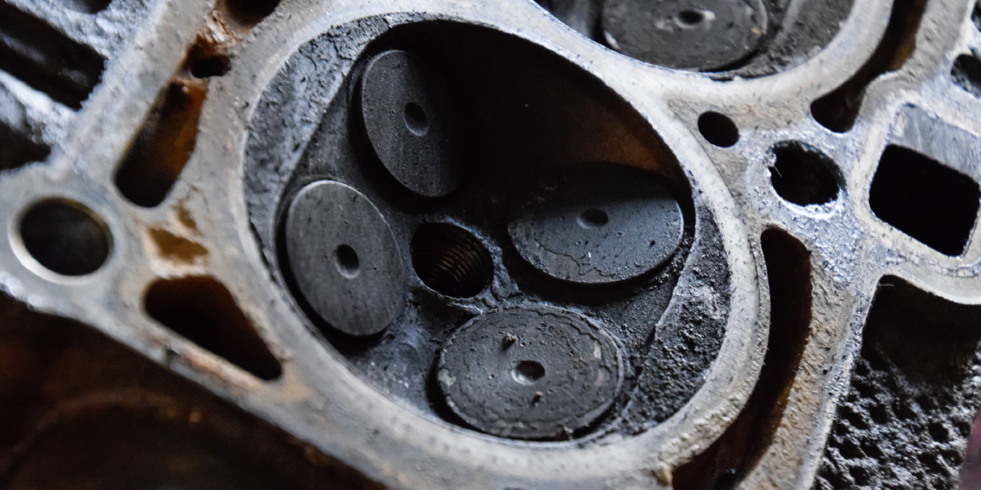
Each series of the FWD VW product has had its share of problems with the clutch system. But in spite of the unconventional design and operation, the clutch on these cars works well, is of sufficient size and is fairly durable with only minimal maintenance required. Except for vehicles with exceptionally high mileage, most clutch failures on these cars can be traced to improper repair, lack of basic maintenance or abuse (See Photos 2 A and B).
For early cars with the manually adjusted clutch cable, maintaining free play is simple but very often overlooked or misunderstood. I’ve seen the cable adjusted improperly at the rate of about 10-to-1 over the last 30 years.
 Very simply, the adjusting portion of the cable has a threaded sleeve that changes the length of the cable housing, which changes the operating length of the cable inside. By backing off the locking nut with a 17mm wrench and holding the outside of the sleeve with a 14mm (OE cables), the threaded end at the transmission can be turned into or out of the sleeve to change the length. The locking nut is then turned gently (metal on plastic) against the bottom of the sleeve to secure the adjustment.
There should be at least a 1/2-inch of free play at the transmission end of the cable, when lifting the cable housing up from the holding fixture. That movement will translate to 3/4- to 1-inch at the pedal. Depending on the condition of the engine mounts, that should provide enough free play to prevent the clutch from disengaging when accelerating as the engine moves.
 With the advent of the self-adjusting cable, routine maintenance should have been eliminated. If driven properly, that is true of most cars, however most drivers still have trouble keeping their foot off of the clutch pedal except for shifting operations or starting from stops.
With even slight pressure constantly applied to the clutch pedal, the cable will progressively get tighter and tighter, and either the clutch will fail, or the release plate will wear through from the constant contact with the release rod. Adjustment reset is easily accomplished as long as the cable has not gotten too tight. By pressing the pedal five or more times, then going under the hood and pressing down on the clutch release lever, the internal mechanism of the cable will release and reset to the proper tension as soon as the clutch pedal is again pushed.
 Disconnecting them from the transmission and then carefully pulling and releasing the cable while holding the sheath can release even cables that have extreme tension due to being at the end of the adjustment. Once the cable is released, the adjuster can be “locked” (See Photo 3) and reinstalled. Normal operation usually resumes after a couple of clutch operations. This has prolonged clutch service life on many cars. So far, failure of the hydraulic release system has been uncommon. Usually, the failure is due to lack of maintenance and allowing the brake master cylinder (shared reservoir for the clutch system) to get too low causing air to enter the clutch system. Bleeding the system after the entry of air can be a challenge, as it always has been with systems that share fluid. The only specific tools needed to rebleed and fill the clutch system are patience and a basic understanding of hydraulics. Put simply, this is a closed system, and once filled and sealed from the entry of air, it will continue to work until there is a leak — either air into or fluid out of the system. There are no adjustments that can be made to allow for wear of the clutch or to change the operational range of the pedal.
 GETTING RELEASE
Very often, the complaint on these cars will be that shifting is difficult, or the clutch will not release at all. Since there is no pilot bearing that has the potential to seize, shifting and release problems are limited to movement of the components that separate the clutch disc from the pressure plate or prevent the separation of the two. Obviously, mechanical failure (broken damper springs, separation of the linings) can also cause these problems, but external causes should be investigated first. Shifting problems can also be from internal transmission failure, but that will require removal of the transmission anyway to check the clutch.
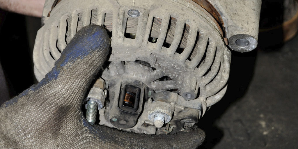
For the cable-operated VW clutch, the release system is different than most other cars. The release bearing is inside the transmission (See Photo 4), so it very seldom fails. The bearing presses against a rod that presses against a plate attached to the diaphragm of the pressure plate, operating much like the release bearing in a conventional clutch. There are a number of places in this system that can cause excess movement that will prevent full release of the clutch.
One of the first places to look, especially if the release lever has excessive movement, is the release “finger” (See Photo 5) that operates the release bearing inside the transmission. It can be accessed through the round cap at the outer end of the transmission housing (the cap may be green or black).
If upon removal the finger is not cracked, the next step is to pull the transmission and look at the release plate. If the contact point of the release rod is off center, or there is a hole in the middle of the plate, then you’ve found the problem. At this end of the release system, even a small amount of wear can cause problems. Although uncommon, the release rod can wear enough to impact release operation. On hydraulic systems, if there are no leaks, but the pedal goes to and stays at the floor, the clutch release arm, bearing or pressure plate has probably failed. Checking operation of the slave cylinder is difficult, as it will blow apart if operated out of the car.
CLUTCH REPLACEMENT
Rather than giving a complete step-by-step procedure for replacing the clutch, I’ll just go through the process with tips on how to avoid additional work or wasted steps. Though I will concentrate on Mk3 and Mk4 cars, these same basic steps are typical for all FWD VWs.
With the car on the hoist, the first steps are done from the top. Since the starter will be removed during the transmission removal, the radio code (for OEM radios) should be obtained and the battery disconnected, or removed in the case of Mk4 cars. I always use an engine support bar, although some techs don’t. This allows additional movement of the engine in the chassis (more on that later).  Install the bar but allow some slack on Mk3 cars so the engine can be lowered slightly later on.
Removing the top bellhousing bolts, ground cable and starter wiring is easier at this point. In addition, the shift linkage or cables can be disconnected along with the clutch cable (release and lock the self-adjusting cable as indicated above) or slave cylinder. The external slave cylinder can be removed while attached to the hose, to prevent the need to rebleed the system. Later cars require the hydraulic hose for the internal slave cylinder to be disconnected.
On Mk3 cars, (See Photo 6) I remove the bolt from the top of the front engine mount and the top of the rear (left or transmission mount), as well as the speedometer cable or speed sensor and backup light switch wiring. On Mk4 cars, the left-side transmission mount and bracket comes off.
With the car raised, remove the left-front tire and lower engine shields. Unbolt the axle shafts from the transmission drive flanges, and remove the left side axle. Remove the starter. With the engine pushed up slightly with an under hoist jack, remove the front motor mount bracket and rear mount bracket and shifter bellcrank on Mk3s. On Mk4 cars, remove the torque strap to the suspension cradle. The engine can now be lowered slightly and hang from the support bar on Mk3 cars. There may be a small cover on the back of the engine covering the opening in the bellhousing, as well as a plate on the bottom of the bellhousing (remove them). There is no need to drain the transmission fluid. If this is an early car with a speedometer cable, a plug can be installed to prevent fluid leakage from the hole when the cable is removed.
On most Mk4 cars, there is room to remove the transmission without repositioning the engine in the chassis. On Mk3 cars, use a jack (the car’s own jack works well for this) or a wedge to push the engine forward away from the cradle a few inches. All of these cars are pretty compact when removing the transaxle.
The process for removing the transaxle after removing the bolts is as follows. The tranny needs to rotate horizontally counterclockwise to pull the input shaft out of the clutch. Then the differential is lifted vertically (transaxle counterclockwise) to align the right-side drive flange with the relief in the engine block, and then rotated clockwise toward the front of the car before lowering out of the car.
This process can be done by one person with a transmission jack but, in reality, we usually team up with another tech and do it all by hand.
Once the transmission is out, inspect it for leaks (See Photo 7), from either the engine or the transaxle. If there is a leak of gear oil, look for any indications of cracks or impact damage inside the bellhousing. Clutch explosions or internal transmission failure can poke holes in the tranny housing. Another, but less likely, leak point is the transmission input shaft seal, or the small seal at the end of the input shaft for the internal release rod. If the release rod seal is bad, plan on putting in a bushing too; it’s just under the seal.
For cars with a cable-operated clutch, remove the flywheel from the pressure plate. The bolts are at the outer rim of the flywheel and will take a 9mm, 12-point socket. The clutch driven disc will come off with the flywheel. Take the normal precautions to avoid clutch dust getting into or on you. On modular clutch models, just remove the entire clutch assembly by removing the crankshaft bolts.
Remove the release plate by prying the retainer out of one of the holes and then rotating it to remove it from the other hole and free the plate. Remove the pressure plate from the crankshaft, noting that the holes are not equally spaced, so the pressure plate can be installed in only one position. If the crankshaft seal shows any leakage, remove the tin plate from the engine block.
On cars with the hydraulic release mechanisms, the process is a little more conventional. The release bearing is either clipped to the release fork or is bolted to the inside of the tranny, and is a combination slave cylinder and release bearing.
As mentioned above, the clutch can be installed in only one position on the crankshaft due to the uneven spacing of the bolts. But, the flywheel on early cars can be installed in the wrong position if the correct components are not used (one or two dowel pins) or the locating pins are removed for resurfacing and not reinstalled.
 Some replacement flywheels also have a different-sized dowel pin. Make sure the clutch kit (See Photo 8) you get has the correct components that match whichever flywheel you intend to use. The most critical fit question is whether the pressure plate will seat on the bolt step when bolted down. A mismatch will not allow the pressure plate to drop fully into the flywheel (make a test fit before bolting the pressure plate to the crankshaft), and cause the clutch to slip.
Reassembly is just the reverse of the removal process, with a few special things to look for. If you’re replacing the rear crank seal (See Photo 9), get the “kit” that has the installer included. This little piece of plastic makes the installation of the seal easier and you’ll be less likely to damage the seal during installation.
Once the clutch verification is done, the pressure plate is bolted to the crankshaft. Whether you have the early or late-type clutches, you must seal the bolts that hold the assembly to the crankshaft. This is because the holes in the crankshaft go through into the crankcase and can leak oil onto the clutch. Some clutch bolts on these cars are “stretch” type, so follow tightening directions based on the bolt type and torque specifications.
On modular clutches, just bolting the assembly in place is all that’s needed. On early-type (cable) cars, be sure to install the release plate (See Photo 10) and clip (make sure it’s completely installed) before installing the disc (See Photo 11) and flywheel. The flywheel bolts for this type of clutch are small and can be easily broken if they’re over tightened, with disastrous results, so follow the torque specs.
Completion is just the reinstallation all of the components that were removed. If you were careful when removing the shift components, no readjustments will be needed.
FINISHING UP
With the number of FWD VWs being driven on a daily basis, and no real end to the sale of new ones in sight, learning some of the peculiarities of the various models can make a clutch job a quick and easy process. After a couple of these jobs, the number of parts that need to be removed is reduced to a minimum and good time can be made on the job by any competent technician.