Some 2012–‘13 model year Camry vehicles may exhibit a condition where ABS brake actuator pump motor noise is heard from the engine compartment with Brake ABS and/or TRAC warning lamp(s) illuminated and DTC C1431 stored. A poor ground on the left fender side panel bracket may cause this condition after a collision repair. This may occur during body shop repairs or other repairs where the left side fender bracket grounds were left loose and not properly attached using the correct bolts, or were improperly painted.
Repair Procedure
1. Follow the Repair Manual procedure to diagnose DTC C1431.
Refer to the Technical Information System (TIS) applicable model and model year in the service information.
2. If the brake pedal load-sensing switch is judged Ok, check the resistance at connector A40 Pin 1 to body ground. Is the resistance always below 1 ohm?
YES: Continue diagnosis using the Repair Manual.
NO: Proceed to step 3.
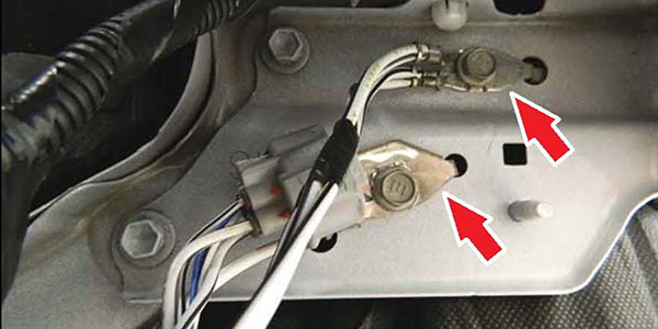
3. With the battery connected, perform a voltage drop test from the two left fender bracket ground wire eyelet tabs to body ground (see Figure 1).
CAUTION: At NO time should the battery be connected when any ground attachments (A1, A2, or apron mounting bolts) are loose.
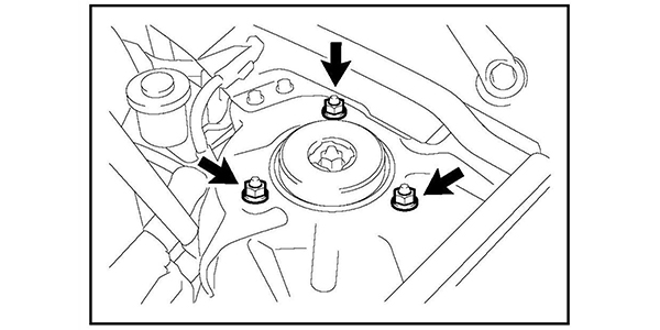
A. Use a left front strut tower mounting bolt as a good body ground (see Figure 2).
B. To perform a voltage drop test, connect the negative lead of the DVOM to the strut tower bolt and the positive lead to the ground wire eyelet tab.
NOTE: Poor contact at the ground at the left fender side panel bracket may be an intermittent condition.
4. Is the voltage drop from each ground location less than 0.2 volts?
YES: Continue diagnosis using the applicable service information.
NO: A voltage drop of 0.2 volts or more from either of the ground locations may indicate poor continuity in the ground circuit. Proceed to step 5.
5. With the battery disconnected, remove the left-hand fender bracket from the apron for inspection.
6. Inspect the grounds on the left-hand fender bracket. Confirm the following:
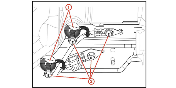
• Ground bolts are “E” bolts (see Figure 3).
• Apron bolts should be “E” bolts if the left-hand fender bracket has been replaced (see Figure 3).
• The area around the bracket to apron mounting bolt holes (see Figure 4) is free of paint.
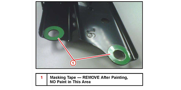
• The area around the apron mounting bolt holes does not show masking tape or painted masking tape (see Figure 4).
If ALL conditions above are met, continue with the diagnosis using the applicable service information.
If ANY of the conditions above are NOT met, continue to step 7.
7. Is there masking tape, painted masking tape or paint around the apron bolt holes?
NO: Replace the left-hand fender bracket.
YES: Remove the tape or paint and continue to step 8.
NOTE: Apply cavity wax to the apron bolts and the area surrounding the washers once the bracket is completely installed.
8. Once the areas are repaired and secured with new “E” bolts, replace the Engine Junction Block Assembly.
9. Confirm there is no damage to the Engine Room Junction Block Assembly.
10. With the battery reconnected, perform another voltage drop test from both ground wire tabs to a strut tower bolt, and verify the voltage drop is less than 0.2 volts.
Is the voltage drop less than 0.2 volts?
YES: Continue to step 11.
NO: Go back to step 6.
11. Perform another resistance check at connector A40 Pin 1 to body ground to confirm that resistance is always below 1 ohm.