Following a cold soak in subfreezing ambient temperatures, some 2003-’08 Corolla and Matrix vehicles equipped with a 1ZZ-FE engine may exhibit an MIL on with one or more of the following DTCs as the result of a vacuum leak at the intake manifold.
– P0171 – System Too Lean (Bank 1)
– P0300 – Random Multiple Cylinder Misfire Detected
– P030 # – Cylinder (1-4) Misfire Detected
– P0133 – Oxygen Sensor Slow Response (Bank 1, Sensor 1)
Inspection Procedure:
The vehicle must be diagnosed following a cold soak. If the vehicle is at operating temperature, the condition will not be present.
1. Monitor the following Data List parameter: Short FT #1 (Short Term Fuel Trim for Bank 1).
Using TIS techstream, select:
Connect to Vehicle/Engine and ECT/Data List/Short FT #1.
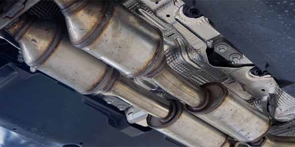
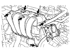
2. Following the conventional diagnostic procedure, confirm if there is a leak where the intake manifold and cylinder head meet between each intake runner. See Fig. 1.
3. Did the short-term fuel trim change to a rich reading (negative fuel trim) in step 2?
– If YES, replace the intake manifold gasket.
– If NO, check for other vacuum leaks or lean-running conditions per the Technical Information System (TIS).
Repair Procedure:
1. Drain the engine coolant. Refer to TIS:
– 2003 or 2004 Corolla Repair Manual, Engine/Hybrid System – Cooling – “Coolant: Replacement”
– 2005 Corolla Repair Manual, Engine/Hybrid System – Cooling – “Engine Coolant (1ZZ-FE): Replacement”
– 2006, 2007 or 2008 Corolla Repair Manual, Engine/Hybrid System – Cooling – “1ZZ-FE Cooling: Coolant: On-Vehicle Inspection”
2. Remove air cleaner hose No. 1.
a. Disconnect the VSV connector.
b. Remove the engine wire clamp.
c. Disconnect fuel vapor feed hose No. 1 and then No. 3 from the VSV.
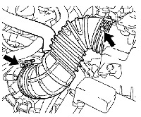
d. Loosen the two hose clamp bolts, then remove air cleaner hose No. 1. See Fig. 2.
3. Remove the intake manifold.
a. Remove the two engine wire clamps from the clamp bracket.
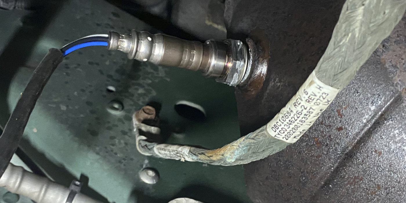
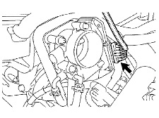
b. Disconnect the throttle control motor connector or accelerator cable (if equipped). See Fig. 3.
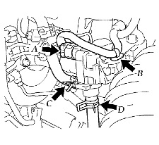
c. Disconnect the water bypass hose and then hose No. 2 from the throttle body.
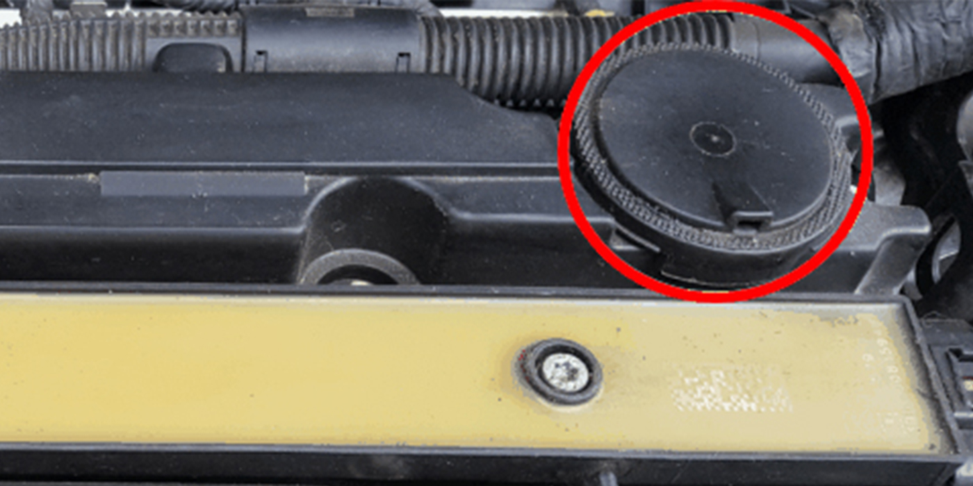
d. Disconnect the union to check valve hose from the intake manifold. See Fig. 4.
e. Remove the four bolts, two nuts and two clamp brackets.
f. Remove the intake manifold and throttle body.
g. Remove the gasket from the intake manifold.
4. Clean the mounting surface of the intake manifold.
5. Install the intake manifold.
a. Install a new gasket onto the intake manifold.
b. Install the intake manifold and throttle body assembly with the two brackets, four bolts and two nuts. Uniformly tighten the bolts and nuts in several passes. Torque: 30 Nm (22 ft.-lbf.)
c. Connect the union to check valve hose to the intake manifold.
d. Connect the water bypass hose No. 2 then the water bypass hose to the throttle body.
e. Connect the throttle control motor connector.
f. Install the two engine wire clamps onto the clamp bracket.
6. Reinstall air cleaner hose No. 1.
a. Install air cleaner hose No. 1 with the two hose clamp bolts.
b. Connect the fuel vapor feed hose No. 3 and then No. 1 to the VSV.
c. Install the engine wire clamp.
d. Connect the VSV connector.
7. Fill and check the engine coolant. Again refer to the appropriate manual on the TIS.
8. Clear the fuel trim values by disconnecting the negative (-) battery cable for 90 seconds.
9. Test-drive the vehicle and confirm normal operation.
Courtesy of ALLDATA.