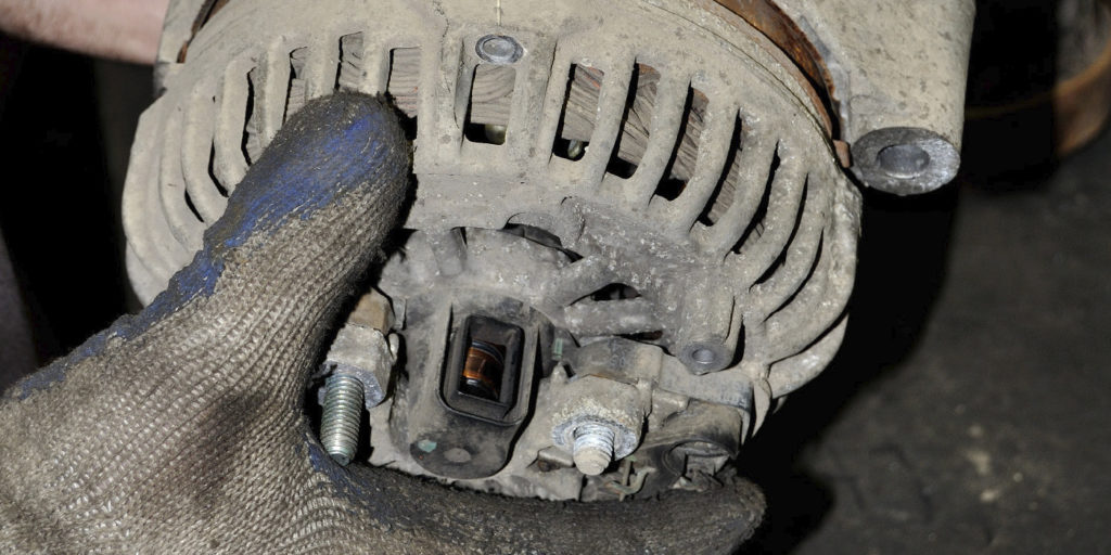
Under certain conditions, customers with various 2002 Camry and Solara, and 2001-’02 Highlander and RAV4 vehicles may experience an MIL on condition with DTC P1349, indicating a variable valve timing (VVTi) malfunction. In some cases, the cause of this DTC may be the VVTi actuator. Use the procedures in this bulletin to verify the operation of the actuator.
Production Change Information:
Chart 1 refers to applicable vehicles produced before the VINs shown.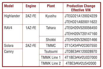
Repair Procedure:
1. Make sure the vehicle is at rest, in Park with the engine idling.
2. Referring to the screen flow shown in Fig. 1, connect the Toyota Diagnostic Tester to the vehicle and select the VVT Control Bank One Active Test (VVT CTRL B1) from the Active Test Menu.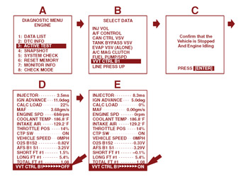
3. Using the right arrow key, toggle the VVTi actuator on.
4. If at this point the vehicle does not run rough and/or stalls when the active test is performed, proceed with Repair Manual P1349 VVTi Fault Isolation Procedure (FIP).
If the vehicle stalls and/or runs rough, it indicates that the VVTi control system is operating. Proceed to replace the VVTi actuator following the repair procedures listed on the Technical Information System (TIS): Engine Mechanical Section, Camshaft, Replacement.
Camshaft Timing Gear Assembly Installation:
1. The camshaft timing gear should come in the unlocked position from the factory. If it’s difficult to install the camshaft timing gear, the lock pin may be engaged. To disengage the lock pin, apply and hold approximately 20 psi of air pressure at the oil feed hole located 90 degrees clockwise of the oval slot. (See Fig. 2.) Once the pin has released, turn the interior assembly counterclockwise. (See arrow in Fig. 2.)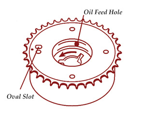
2. Put the camshaft timing gear assembly and the camshaft together with the straight pin off the key groove.
3. Turn the cam-shaft timing gear assembly (as shown in Fig. 3) while pushing it lightly against the camshaft. Push farther at the position where the pin fits into the groove.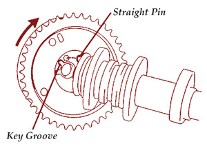
Note: Be sure not to turn the camshaft timing gear to the retard angle side (in the clockwise direction).
4. Check that there is no clearance between the end of the camshaft and the camshaft timing gear.
5. Tighten the camshaft bolt with the camshaft timing gear fixed. Torque: 54 Nm (551 kgf.cm, 40 ft.-lb.)
6. Check that the camshaft timing gear assembly can move to either side and is not locked.
Courtesy of Mitchell 1.