 Looking at the TSBs from the manufacturers’ websites, both the Vibe and Matrix are relatively trouble free with no recalls for the brake system. While these vehicles are not prone to abnormal brake noise, both GM and Toyota have advise on their sites that technicians should pay attention to hardware and shims when performing a brake job.
Front Brakes
1. Remove the caliper slide pin bolts.
2. Pull the caliper and hang it from the strut. Inspect the piston boot for any damage.
3. Remove the outer pad and push back the piston with the appropriate tool. You can restrict the brake hose with a non-damaging tool and relieve the pressure through the bleeder. But, GM nor Toyota does not recommend this procedure.
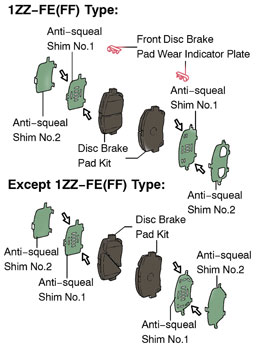
4. Remove the inner pad. If the pads are original, it will have a two-piece shim on each pad. Make a note of the positions of all four shims and clips.
5. Using a ruler, measure the pad lining thickness. Max: 11.0 mm (0.433”) Min: 1.0 mm (0.039”).
6. Remove the bolts that hold on the caliper bracket.
7. Inspect caliper bracket for damage and corrosion.
8. Measure the pad thickness. The standard thickness is 25 mm (0.984”). The Minimum thickness: 23 mm (0.906”).
9. Make “matchmarks” on the front disc and the axle hub. Fasten the disc with hub nuts. Torque to 103 n/m 76 ft/lbs.
10. Measure the rotor’s runout 10 mm away from the outer edge of the disc. Toyota specifies a maximum disc runout 0.05 mm (0.0020 in.). If the disc runout is the maximum value or greater, check the bearing play hub flange runout.
Tip: You can lower the runout by changing the position of the rotor on the hub flange. With this technique you can minimize the amount of material removed from the rotor during on-the-car machining. This can make a more thermally stable rotor that absorbs heat evenly and reduces pulsation comebacks.
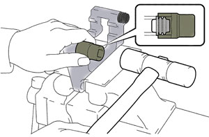 11. Place caliper bracket in a vise. Clean the bracket and replace the abutment clips if necessary. You can also apply a moly-based lubricant to the surfaces that make contact with backing plate of the brake pad. It is recommended that the slides and bushings in the bracket be replaced if the rubber or metal has degraded. To remove or install the pins, Toyota recommends using a socket (19 mm) and hammer to drive the dust boots into the disc brake cylinder mounting. Apply the lithium or silicone base lubricant to seal surface of slide pin’s dust boots.
12. Install the caliper bracket and torque the bolts to 106.8 n/m or 79 ft/lbs.
13. Install the pads. Depending on the type of shim used on the new brake pad, lubricate the recommended areas as indicated by the manufacturer. Do not reuse the old shims. Note: Install the pad wear indicator plate facing upward.
14. Install caliper. Torque the two bolts to 34.3 n/m or 25 ft/lbs.
15. Torque the lug nuts to 103 n/m or 76 ft/lbs.
* If the caliper was replaced, the torque for the union bolt is 29 n/m or 21 ft/lbs. Always install a new copper washers with the union bolt.
 Rear Disc Brakes
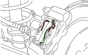
1. Remove the clip, anti-rattle spring no.1 and anti-rattle spring no.2.
2. Remove the pad guide pins and disc brake pads and shims.
3. Remove caliper bolts that hold it to the knuckle.
4. Push back the piston with the appropriate tool. Do not use force to screw the piston into the disc brake cylinder. You can restrict the brake hose with a non-damaging tool and relieve the pressure through the bleeder. But, Toyota and GM do not recommend this procedure.
5. Remove the bushings and slides from the caliper assembly so they can be replaced or cleaned and lubricated.
6. Using a ruler, measure the pad lining thickness. Standard thickness: 10.0 mm (0.394”) Minimum thickness: 1.0 mm (0.039”) .
7. Inspect rotor thickness. Standard thickness: 9.0 mm (0.354”) and minimum thickness: 7.5 mm (0.295”)
8. Measure the disc runout 10 mm away from the outer edge of the disc.
Maximum disc runout: 0.05 mm (0.0020”.). If the disc runout is the maximum value or greater, check the bearing play in the axial direction and check the hub flange for runout. Also, you can lower the runout by changing the position of the rotor on the hub flange. With this technique you can minimize the amount of material that is removed from the rotor. This can make a more thermally stable rotor that absorbs heat evenly and can reduce pulsation complaints.
9. Install the rotor.
10. Install slide boots. Apply the lithium or silicone based grease to sealing surfaces of the boots. Place the caliper on over the rotor and install the mounting bolts and torque to 46.6 n/m or 34 ft/lbs.
11. Install the pads and shims. Depending on the type of shim used on the new brake pad, lubricate the recommended areas as indicated by the manufacturer. Do not reuse the old shims.
 12. Install the two guide pins to the brake pads.
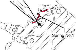
13. Install spring no. 1.
(a) Hook the spring upper portion to the guide pin no.1.
(b) Hook the spring lower portion to the center hole of the pad.
14. Install spring no. 2.
(a) Hook the spring upper portion to the guide pin no. 1.
(b) Hook the spring lower portion to the center hole of the pad.
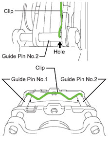
15. Fix guide pins with clip
(a) Insert the clip end into the hole of the guide pin no. 1.
(b) Insert the other clip end into the hole of the guide pin no. 2.
The clip should be fully inserted into the guide pin no. 1 and No. 2. If not, the guide pins will come off and the caliper will be 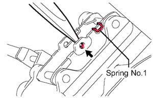 damaged when the brakes are applied.
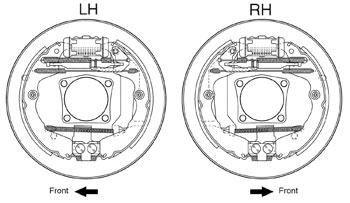
Adjusting Rear Drums
1. Perform this adjustment with the wheel off.
2. Remove the hole plug, and turn the adjuster and expand the shoe until the drum locks.
3. Using a screwdriver, back off the adjuster 8 notches.
4. Install the hole plug.
5. Normal brake actuation will bring the clearance into optimal adjustment.
Adjusting the Parking Brake
 1. Pull the parking brake lever to the fully applied position, and count the number of clicks. The parking brake lever should travel 5 to 8 clicks with a moderate pulling force.
2. To adjust, remove the rear console box sub-assembly.
3. Loosen the lock nut and turn the adjusting nut until the lever travel is correct.
4. Tighten the lock nut to 5.0 n/m or 44 in/lbs.
Bleeding
The Matrix and Vibe can be bled conventionally. But, if the ABS modulator/actuator has been replaced or the pedal is still soft or low, it will require a scan tool to bleed the system. Just remember to depress the brake pedal more than 20 times with the engine off to let the vacuum pressure out from the brake booster assembly before bleeding.