Rich Diegle
Senior Automotive Editor
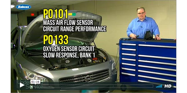
If one of the following vehicles comes into the shop with the “Malfunction Indicator Lamp” (MIL) “ON” and one or more of the following Diagnostic Trouble Codes (DTCs) are stored in Engine Control Module (ECM), the repair may be as simple as installing an additional ground sub-harness.
Vehicles:
• 96-97 Pathfinder: DTC P0130, P0150, P0136, or P0156
• 98-00 Pathfinder: DTC P0131, P0134, P0138, P0140, P0151, P0154, P0158, P0160
• 99-01 Frontier (V-6 Engine Only): DTC P0131, P0134, P0138, P0140, P0151, P0154, P0158, P0160
• 00-01Xterra (V-6 Engine Only): DTC P0131, P0134, P0138, P0140, P0151, P0154, P0158, P0160
• 02-04 Frontier (V-6 Engine Only): DTC P1143, P0134, P0138, P1163, P0154, P1146, P1166, P0158
• 02-04 Xterra (V-6 Engine Only) DTC P1143, P0134, P0138, P1163, P0154, P1146, P1166, P0158
If you retrieve these codes, use the following manufacturer’s Diagnosis and Service Procedure to confirm and repair the condition. You MUST closely follow the entire Service Procedure as it contains information that is essential to successfully completing this repair.
Diagnosis and Service Procedure
Review safety procedures in ALLDATA Repair before beginning.
1. Check for poor grounding using a Digital Volt-Ohm Meter (DVOM).
2. Measure the voltage drop between the intake manifold ground bolt for the engine harness and the right hand (RH) cylinder head.
3. At engine warm idle, place the positive (red) meter lead on the intake manifold ground bolt for the engine ECCS harness and the negative (black) lead on RH cylinder head and measure the voltage.
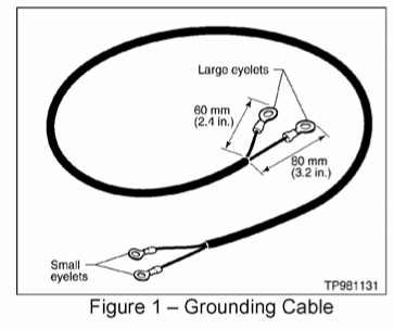
• If the voltage is above 0.025V (25 millivolts), install the sub-harness shown in Figure 1 to resolve the incident. Continue with step two of this bulletin.
• If the voltage is less than 0.025V (25 millivolts), the problem will not be repaired with a sub-harness and will require further diagnosis. Refer to the System Diagnosis section in ALLDATA Repair.
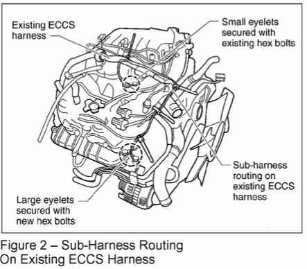
4. Route the sub-harness from the RH cylinder head, on the existing ECCS harness. Route it toward the center front of the engine and then back toward the intake manifold collector (Figure 2).
5. Find the two threaded holes in the RH cylinder head next to the negative battery cable attachment point (Figure 3).
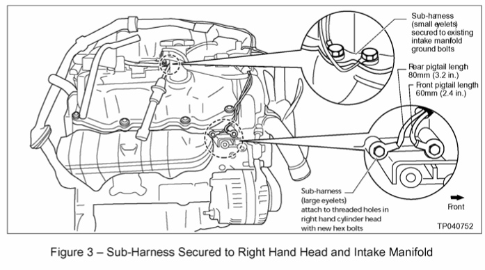
6. Secure the sub-harness end with the two larger eyelets to these two threaded holes (Figure 3).
7. Use the two new hex bolts to attach the sub-harness eyelets.
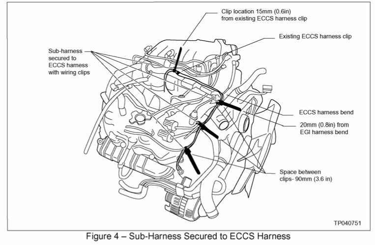
Caution: To prevent damage, the sub-harness must be positioned more than 70 mm (2.8 in.) from the exhaust manifold.
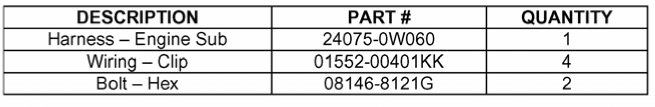
8. Now attach the sub-harness to the ECCS harness at four (4) places (Figure 4) using the wiring clips listed in the parts information. Space the wiring clips out as shown in Figure 4.
9. Secure the sub-harness end with the two smaller eyelets. You’ll attach them using two of the existing ground bolts located on the intake manifold (Figure 3).
10. Trim the excess material from the newly installed wiring clips.
Written by ALLDATA Senior Automotive Technical Editor, Rich Diegle. Rich is an Advanced Engine Performance Certified, ASE Master Technician with an AA Degree in automotive technology and 23 years of dealership and independent shop experience.
For additional information, visit www.alldata.com.