Applied vehicles: 1996-2000 Pathfinder (R50), 1999-2004 Frontier (V6 Engine Only) and 2000-’04 Xterra (V6 Engine Only)
If an applicable vehicle shows the MIL on and one or more of the following DTCs are stored in the ECM:
– 1996-’97 Pathfinder: DTC P0130, P0150, P0136 or P0156;
– 1998-2000 Pathfinder: DTC P0131, P0134, P0138, P0140, P0151, P0154, P0158 or P0160;
– 1999-2001 Frontier (V6 Engine Only) or 2000-’01 Xterra (V6 Engine Only): DTC P0131, P0134, P0138, P0140, P0151, P0154, P0158 or P0160; or
– 2002-’04 Frontier (V6 Engine Only), 2002-’04 Xterra (V6 Engine Only): DTC P1143, P0134, P0138, P1163, P0154, P1146, P1166 or P0158
then use the Service Procedure to diagnose and repair the incident (if it should occur).
– Perform a voltage drop test to check for a poor “ground” condition.
-If necessary, install a sub-harness between the intake manifold and the cylinder head to provide a direct path to “ground.”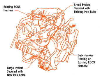
Service Procedure:
1. Check for poor grounding using a digital volt-ohm meter (DVOM).
– You’ll measure the voltage drop between the intake manifold ground bolt for the engine harness and the right hand (RH) cylinder head.
– At engine warm idle, place the red meter lead on the intake manifold ground bolt for the engine ECCS harness and the black lead on RH cylinder head and measure the voltage.
a. If the voltage is less than 0.025V (25 millivolts), this bulletin does not apply.
b. If the voltage is above 0.025V, install the sub-harness to resolve the incident. Continue with step 2.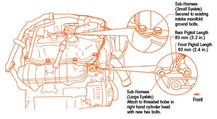
2. Route the sub-harness from the RH cylinder head, on the existing ECCS harness. Route it toward the center front of the engine and then back toward the intake manifold collector (see Fig. 1).
3. Find the two threaded holes in the RH cylinder head next to the negative battery cable attachment point (see Fig. 2).
– Secure the sub-harness end with the two larger eyelets to these two threaded holes.
– Use the two new hex bolts to attach the sub-harness eyelets.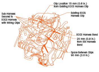
Caution: To prevent damage, the sub-harness must be positioned more than 70 mm (2.8”) from the exhaust manifold.
4. Attach the sub-harness to the ECCS harness at four places (see Fig. 3) using wiring clips. Space the wiring clips out as shown in Fig. 3.
5. Secure the sub-harness end with the two smaller eyelets. Attach them using two of the existing ground bolts located on the intake manifold (see Fig. 3).
6. Trim the excess material from the newly installed wiring clips.
Courtesy of Mitchell 1.