Use the following procedure to replace the fuel pump connector on 1993 and newer 850, S70, V70 and C70 models.
Service Procedure
1. For five-door vehicles, remove the four screws from the floor hatch, pull the hatch backward and lift it out.
For four-door vehicles, remove the floor mat, loosen the right panel at the front edge and fold it away.
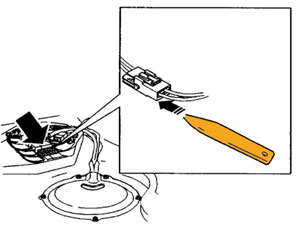
2. For five-door vehicles, remove the connector from the bracket by pushing the lock down using a small screwdriver (1/8”-5/32” wide), then push the connector toward the right side of the car. See Figure 1.
Separate the connector.
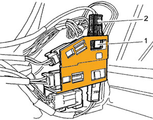
For four-door vehicles, remove the connector from the holder by pushing the lock (1) outward using a small screwdriver (1/8”-5/32” wide), and then pushing the connector (2) upward. See Figure 2.
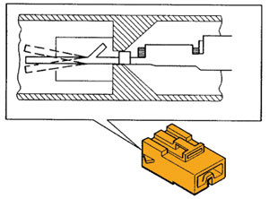
3. Check that the wire terminals are centered in the connector socket insulators. Carefully wiggle the wires to make the terminals move. Replace the connector if the terminals can be moved farther in both directions, than what Figure 3 shows. Replace the connector and terminals if any terminal is bent.
4. Check the corners in the slot of the connector to make sure they’re undamaged. Replace the connector and terminals if any slot or terminal is damaged.
5. Cut the wire 10 mm (3/8”) from the connector.
6. Strip the wires 5-6 mm (3/16-1/4”). It’s recommended to use stripping pliers that can be set for stripping distance and wire diameter.
7. Insert the stripped ends into the butt-connector. Ensure that the color-coding matches before crimping. Note: Do not twist the wires.
8. Use tool #951 2656 to crimp the wires. Check that the wires are firmly attached by carefully pulling on them.
9. Before sealing the butt-connectors, protect the interior and other wiring from the heat. Carefully heat the connector until the shrink tube seals the connector ends.
Warning: Use a hot air gun with the heat setting in low. Do not touch the surface after finishing work; the connector is hot.
10. If the shrinkage is properly done, glue should be protruding from the ends of the shrink sleeve.
11. Install the connector to the bracket.
12. Start the engine and ensure engine operation.
13. Reinstall the interior in reverse order.
Courtesy of IDENTIFIX.