 Let’s discuss the 4×4 operation on Ford truck platform vehicles. We’ll cover the operation of the parts on the various rear-wheel-drive 4×4 systems. When it comes to Electronic Shift-On-the-Fly (ESOF) and Manual Shift-On-the-Fly (MSOF), much is the same except with MSOF, the driver has to manually push a gear shifter in the floor that is connected by rods to the shift fork inside the transfer case.
With shift-on-the-fly four-wheel drive, the vehicle does not need to be stopped and placed into neutral to make the selection between 2×4 and 4x4H. The benefits of this for the driver are that they don’t have to get out and lock in hubs at the wheels, and that they are able to maintain momentum of the vehicle to help them get through a situation.
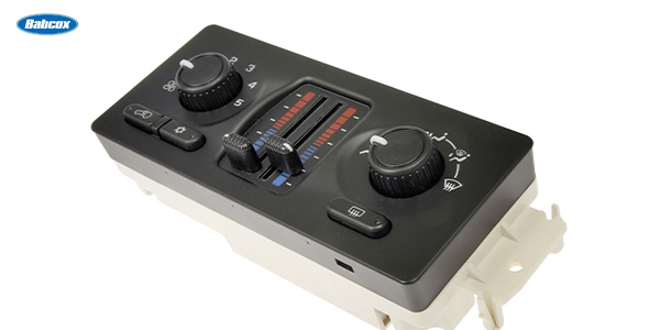
With ESOF, the driver is given either a dial-type switch or push buttons to select 2×4, 4x4H and 4x4L. The driver must actively command 2×4, 4x4H or 4x4L to engage. For A4WD, the driver has a choice of setting dependent on year and model. Some offer 2×4, A4WD, 4x4H and 4x4L, while some exclude the 2×4 setting and only offer A4WD, 4x4H and 4x4L.
To achieve ESOF, the control module watches for input from the four-wheel-drive mode selector switch. The control module in charge of the system will vary depending on the year and model of the vehicle. The control model in command can be the GEM module, the PCM or a dedicated 4×4 module.
A4WD operation can be achieved either electronically by a control module watching speed sensor inputs and automatically engaging 4×4, or this can be done mechanically using a viscous coupling.
Shift Motor
The shift motor is controlled by the control module through two relays by grounding them. The relays are labeled as clockwise and counterclockwise relays, however they both play a part in making the motor turn in either direction. These relays have a dual pole switch side to them. These types of relays are often referred to as a five-blade relay. The clockwise relay supplies B+ power to the motor to make it turn in the clock while the counterclockwise relay is providing the ground path. This process is inverse for making the motor turn counter clockwise.
The module “knows” the position of the motor based on feedback from the contact plate that forms a series of switches. Most commonly, this contact plate is located on the back of the motor.
 Synchronous Clutch
A synchronous clutch is really just a manual transmission synchronizer. The command for 4×4 from the module results in the shift motor, that is very similar in appearance to a window or wiper motor, to be rotated. The electric motor turns a camshaft inside the transfer case. As the shaft turns, it moves a shift fork. The fork then slides a synchronizer ring and hub. That hub then puts pressure on three rings. These rings, called blocking rings, have a conical formation so that the outer ring wedges over the middle ring. Then the middle ring wedges over the inner ring.
The inner ring has tabs that are always locked into a clutch gear that turns a drive sprocket. The drive sprocket and gear just free wheel over the rear output shaft on bushings when in 2×4 mode. But when the blocking rings are forced against one another, the wedging action causes the power from rear output shaft to be transferred to the drive gear causing the drive gear and sprocket to spin up to match the rear output shaft’s speed. Once this happens, the locking collar continuous to move a little more until it slides part way off of the clutch hub and over top of the drive gear.
The outer edge of the drive gear has teeth that mate with the inside edge of the collar so that a solid mechanical lock-up will have occurred from the hub, to the collar, then the gear. Now the drive sprocket is turning a chain which is turning a driven gear mounted on the output shaft and power can then flow to the front axle.
Electromagnetic
There are two different designs of electromagnetic clutches — TOD and standard design. Though there are some mechanical detail differences between the standard and TOD clutch, their basic operation, as viewed from outside the case, is the same.
If the control module sees a speed difference between the front and rear output shafts, it will energize the electromagnetic field of the clutch pack to engage the clutch. When the clutch is engaged, the drive chain then transfers power to the front output shaft. If the vehicle has A4WDR and 4H selector positions on the switch, then the operation of the clutch is the same except for that in 4H position, the clutch will be continuously engaged rather than only being commanded on when a speed difference in shafts is detected.
Viscous Coupling
The viscous coupling is completely mechanical. The clutch housing is a sealed unit. Inside the unit are a series of clutch discs, drive and driven plates. In with the discs are a silicone fluid. As the drive discs turn within the assembly, the fluid is sheered between the drive and driven plates. This action transfers power to the front output shaft via the driven plates regardless of the amount of traction available at the wheels. If the rpm differ enough between the rear output shaft and front output shaft, the fluid will be sheered at a higher rate causing the fluid to heat up. If the fluid gets hot enough, it will expand and cause the plates to be forced together and lock. The unit will unlock as it cools, and the cycle repeats as needed.
Locking Hubs
For many vehicles, the hubs provide a connect and disconnect point between the wheels and the front differential. This connect/disconnect point allows the front axle and differential to rest when not in use and only be active when needed. This reduces the number of moving parts while in 2×4 mode, not only for wear reasons, but to prevent these extra moving parts from unnecessarily lowering fuel economy through increased rolling resistance.
For Ford vehicles, there are three different types of locking hubs. There is also another method of disconnect used that is not performed at the hubs, but rather on the axle assembly, for a total of four different methods of connecting and disconnecting the motion between the front wheels and the front driveshaft.
Manual Hubs
Manual hubs are not found on shift-on-the-fly systems as they require the driver to exit the vehicle and manually turn from “free” to “lock” positions. Inside of a manual locking hub is a dial mechanism, activation spring, inner drive gear, clutch ring, release spring and support. These parts sit inside of a housing that is supported at one end by the dial mechanism and by the support at the other end. The support has bearings in the inner race of it that allow the assembly to freewheel intendant of the axle as needed.
When dialed to the lock position, the cam portion of the dial mechanism presses against the engagement spring. The spring then provides pressure against the inner drive gear. That causes the clutch ring to be pushed so that its inner spines are pushed over the outer spines of the inner drive gear. The outer portion of the clutch ring is splined to the support which is splined and mounted to the dial mechanism that is bolted to the hub/rotor. The inner drive gear is splined to the axle shaft. Now, there is a solid mechanical lock from the axle to the front wheels via the axle to the inner drive gear, to the clutch ring, to the housing, to the dial mechanism to the hub.
When the dial is selected back to “free,” then the pressure of the activation spring is released which allows the release spring to push the clutch ring so that the clutch ring’s inner splines side off of the outer splines of the inner gear. During usage, the clutch ring may be bound to the inner gear due to driveline windup and may not instantly release. That is why the driver may need to back the vehicle up a few feet. That releases the pressure between the splines so that the release spring can do its job.
PVH
Pulse Vacuum Hublock (PVH) hubs have an outward appearance similar to manual hubs. One notable difference is that the two manually selected positions on the hub are “lock” and “auto.” When in “lock,” the hub engages the same way as a manual locking hub. In “auto,” vacuum is used to engage and disengage the hub.
Typically, there will be a PVH solenoid located on the inside of the right front inner fender. For F-series platform vehicles, that will place the solenoid close to the battery. The PVH solenoid contains two coil windings and will have three wires going to it. One wire is B+ voltage and the other two are ground wires with separate circuits to the control module.
When the driver selects 4×4 mode, the control module grounds both coil windings. With both coil windings grounded, the solenoid sends approximately 18 inches of vacuum for gasoline vehicles and about 15 inches of vacuum for diesel vehicles for 45 seconds. Vacuum for diesel vehicles comes from an electric vacuum pump. This vacuum is routed to the hubs.
This high level of vacuum causes the clutch ring to engage the inner gear and lock into position. The vacuum does not need to be continuously applied to this design because the engagement is mechanically held after vacuum is released. When the driver selects 2×4, only one of the coils is energized which sends a lower vacuum to the hubs. This lower vacuum is only about six inches. This lower level of vacuum only partially activates the hub which causes it to partially disengage the clutch ring from the inner gear.
That vacuum times out after 15 seconds. At the end of the 15 seconds, the release spring can then push the clutch ring off of the inner gear. Think of it like the action of a push-button pen. You fully press the button and release to engage the lock that continues to hold the writing tip out even though you aren’t pressing on the button. Then, push the same button only partially compared to before, and release it to let a spring complete the process.
IWE
Integrated Wheel End (IWE) hubs are a vacuum-operated locking hub that differs from the PVH in operation. With IWE, there are splines on the back of the hub and on the end of the axle halfshaft’s CV joint housing. The IWE locking mechanism mounts between the hub’s splines and the CV joint’s housing splines. The IWE unit consists of vacuum and vent ports, internal spring, vacuum diaphragm, plastic fork and lock-up collar. The default position, no vacuum, 4×4 is engaged by the spring inside the IWE. The spring pushed the lock-up collar from the CV housing splines toward the hub splines so that the lock up collar straddles the air gap between the CV housing splines and the hub splines. This provides a mechanical lock from the axle to the hub through the collar.
When 2×4 is selected, vacuum is then applied to the vacuum diaphragm which slides the locking collar off of the hub’s splines. Vacuum is maintained during 2×4 operation. If vacuum is lost for any reason, the hubs will engage.
Vacuum is sent to the hubs by the control module grounding the IWE solenoid. This solenoid is commonly found on the right side of the engine compartment and bolted to the firewall.
Center Axle Disconnect
With a center axle disconnect system, a vacuum motor is mounted to the axle housing near the differential. The vacuum motor has two vacuum chambers — an engage side and a disengage side. There are two vacuum solenoids for this system. One solenoid routes vacuum to the engage side of the vacuum motor, and the other to the disengage side.
The vacuum motor operates a shift lever that engages and disengages a collar inside the differential housing. This disengages one axle from the differential, which releases the load from the differential. The load is then released from the front driveshaft.
This concludes the first part of Ford rear-wheel-drive 4×4 systems. As with any system, you can fix it if you first know how it works.
Glen Beanard is ASE-certified as amaster auto technician, ASE truck technician and ASE serviceconsultant, as well as holding ASE certifications in L1 and alternatefuel systems. He has completed 84 Ford training courses in his 17 yearsof combined automotive repair experience between independents, nationalchains, fleet repair shops and dealers, having served as both atechnician and manager.