Affected vehicles: 2005-’07 Ford Five Hundred, Freestyle; 2005-’07 Montego
Issuing a Self Test
Some 2005-’07 Five Hundred, Freestyle and Montego vehicles equipped with all wheel drive (AWD) may exhibit the traction control warning lamp on. If the traction control lamp is on but no DTCs are retrieved, be sure to directly self test the DEM (4X4 module) using the diagnostic scan tool.
Service Procedure
1. Install a diagnostic scan tool and retrieve any available DTCs from the DEM, ABS module and instrument cluster. If there are DTCs in the ABS module or instrument cluster, do not continue with this TSB.
Note: Although the same warning lamp is shared for both systems, the DTCs for the AWD and traction control system are not stored in the Powertrain Control Module (PCM) as on some other Ford/ Mercury vehicles. The DEM (4×4 module) must be selected, as it is an optional module only used on AWD vehicles. Traction control DTCs are stored in the ABS module. Vehicle wiring and communication DTCs related to the AWD and traction control system are stored in the instrument cluster.
2. If DTC codes other than P1889 are present in the DEM, follow additional diagnostic routines and do not follow this TSB procedure.
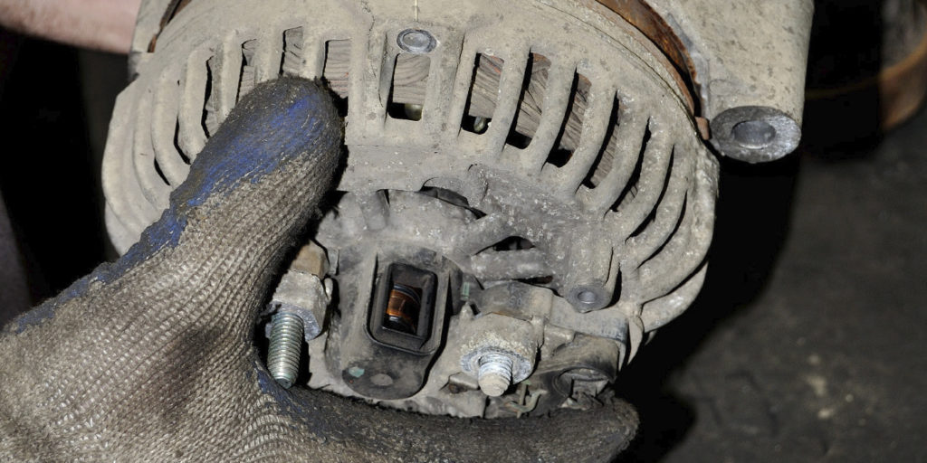
3. If DTC code P1889 is the only code present in the DEM, replace the oil pressure/temperature sensor (4B487) and clear the code.
Note: When replacing the oil pressure/temperature sensor, the O-ring seal on the adjacent solenoid valve must also be replaced.
Note: The solenoid valve normally comes out of the on-demand coupling as the DEM is removed. If it does not, either remove it by hand, or carefully remove it with pliers.
4. Remove the existing O-ring from the coupling body.
5. Install the new O-ring included in the Pressure Sensor Kit, on the solenoid valve.
6. Install the solenoid valve and oil pressure/emperature sensor into the DEM (not into the coupling body) prior to assembling the DEM to the coupling body.
Note: Install the oil pressure/temperature sensor washer with the concave (dished) side facing the DEM.
7. Perform a test drive.
a. Start the engine and allow the vehicle to idle for a minimum of 5 minutes with the transmission in park.
b. Perform five 0-25 MPH (0-40 Km/h) wide-open-throttle accelerations.
Courtesy of Ford Motor Co., TSB 08-4-11