Vehicles:
• 2000-2005 Neon
• 2001-2004 Chrysler PT Cruiser
Symptom/Condition:
Vehicle may exhibit a popping/clicking/snapping/ticking sound from the front hub/half shaft area during acceleration after Drive to Reverse or Reverse to Drive shifts. The sound may also be present while turning and accelerating from a stop.
Diagnosis:
In order to determine if the popping/clicking/snapping/ticking sound is coming from the front hub/half shaft interface, perform the following procedure:
1. Raise the vehicle on an appropriate hoist and remove both front wheels.
2. Remove the cotter pin, nut lock and wave washer from the end of both half shafts.
3. With the vehicle’s brakes applied to keep the hub from turning, loosen both half shaft nuts to zero torque.
4. With the service brake applied, shift the vehicle from Drive to Reverse and Reverse to Drive. Once the transmission is engaged in gear, raise the engine speed to 1800 rpm.
5. If the sound is not present, perform the Repair Procedure. If the sound is still present, the source of the sound is elsewhere. Further diagnosis is required.
Repair Procedure:
1. Raise the vehicle.
2. Remove the half shaft nut.
3. Remove the wheel and tire assembly from the vehicle. Refer to the service information.
4. Remove the two front disc brake caliper adapter to steering knuckle attaching bolts (See Figure 1).
5. Remove the disc brake caliper assembly from the steering knuckle. The caliper assembly is removed by first rotating the top of the caliper assembly away from the steering knuckle and then removing the bottom of the assembly out from under the machined abutment on the steering knuckle.
6. Support the disc brake caliper assembly by using a wire hook and suspending it from the strut assembly (See Figure 2).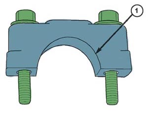
Note: Do not allow the brake caliper assembly to hang by the brake flex hose.
7. Remove the brake rotor from the hub and bearing assembly.
8. If the vehicle is equipped with eccentric bolts attaching the steering knuckle to the strut assembly, proceed to next step. If not, proceed to step 10.
9. Mark the head of the eccentric bolt and the strut, so that the bolt can be installed in the same position later.
10. Remove the wheel speed sensor bolt.
11. Remove the steering knuckle-to-strut attachment bolts from the steering knuckle (see Figure 3).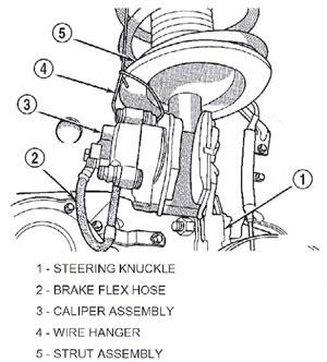
12. Pull the steering knuckle from the strut clevis bracket.
Note: Care must be taken not to separate the inner CV joint during this operation. Do not allow half shaft to hang by inner CV joint after removing outer CV joint from the hub/bearing assembly in steering knuckle. The outboard end of the half shaft must be supported.
13. Pull the steering knuckle assembly down and away from the outer CV joint while pulling the CV joint out of the hub bearing.
14. Support the outer end of the half shaft assembly.
Note: The rubber gasket is to be installed as is (after removing the paper backing). The gasket should not be cut in any way.
15. Slide the gasket/washer, p/n 04809863, over the CV joint splines to the CV joint surface, item 2, shown in Figure 4.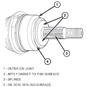
16. Grasp the inner tripod joint and interconnecting shaft. Forcefully push the tripod joint into side gear of the transaxle. Be sure the snap-ring is engaged with the transaxle side gear.
17. Clean all debris and moisture out of the steering knuckle in the area where the outer CV joint will be installed into steering knuckle.
18. Clean the CV joint surface.
19. Ensure that the front of the outer CV joint which fits against the face of the hub and bearing is free of debris and moisture before installing the outer CV joint into the hub and bearing assembly.
20. Slide the half shaft back into the hub assembly.
21. Install the wheel speed sensor bolt and torque it to 12 Nm (105 in. lbs.).
Caution: The steering knuckle to strut assembly attaching bolts are serrated and must not be turned during installation. Install nuts while holding bolts stationary in the steering knuckle.
Caution: If the vehicle being service is equipped with eccentric strut assembly attaching bolts, the eccentric bolt must be installed in the bottom (slotted) hole on the strut clevis bracket (See Figure 5).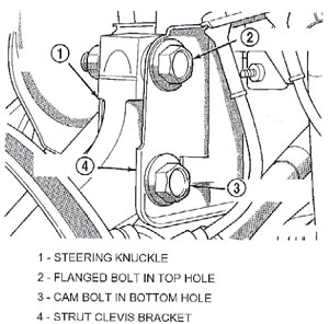
22. Install the steering knuckle in the clevis bracket of the strut assembly. Install the strut to steering knuckle attaching bolts. If the eccentric bolt and strut was marked in step 9, align the marks. Tighten both bolts to a torque of 88 Nm (65 ft. lbs) plus an additional 1/4 turn.
23. Install the brake rotor on the hub and bearing assembly.
24. Install the disc brake caliper assembly on the steering knuckle. The caliper is installed by first sliding the bottom of the caliper assembly under the abutment on the steering knuckle, and then rotating the top of the caliper against the top abutment.
25. Install the disc brake caliper adapter to steering knuckle attaching bolts (Figure 1). Tighten the disc brake caliper adapter bolts to a torque of 169 Nm (125 ft. lbs.).
26. Clean all foreign matter from the threads of the outer CV joint. Install the washer and half shaft nut on half shaft and securely tighten the nut (the nut will be torqued later).
27. Install the front wheel and tire assembly. Install and tighten the wheel mounting stud nuts in proper sequence until all the nuts are torqued to half the required specification. Then repeat the tightening sequence to the full specified torque of 135 Nm (100 ft. lbs.).
28. Repeat steps 2 through 27 on the other side of the vehicle. When steps 2 through 25 have been completed on both sides of the vehicle, lower the vehicle.
29. With the vehicle’s brakes applied to keep the hub from turning, tighten the hub to a torque of 244 Nm (180 ft. lbs.).
30. Install the spring wave washer on the end of the half shaft.
31. Install the hub nut lock, and a new cotter pin. Wrap the cotter pin prongs tightly around the hub nut lock as shown in Figure 6.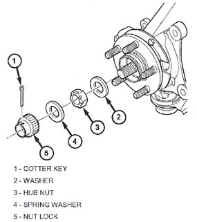
32. Repeat steps 29 through 31 on the other side of the vehicle.
Technical service bulletin courtesy of Mitchell 1.
For more information on Mitchell 1 products and services, automotive professionals can log onto the company’s website at www.mitchell1.com.