Tech Tip: Diagnosing a Ford Escape with Engine Ticking Noises – UnderhoodService

Tech Tip: Diagnosing a Ford Escape with Engine Ticking Noises

If a customer brings in a 2006 Ford Escape with a ticking noise in the left bank cylinder head engine area, refer to the following service procedure to identify and resolve the issue. To diagnose, with the engine running and warm (normal operation temperature), use a mechanic's stethoscope to determine if the ticking noise is coming from the ....

If a customer brings in a 2006 Ford Escape with a ticking noise in the left bank cylinder head engine area, refer to the following service procedure to identify and resolve the issue.

Vehicles affected: 2005-’07 Five Hundred, Freestyle Montego, 2006-’07 Fusion and Milan, 2006 Zephyr, and 2006-’08 Escape and Mariner vehicles built 1/17/2006 through 5/31/2007, 
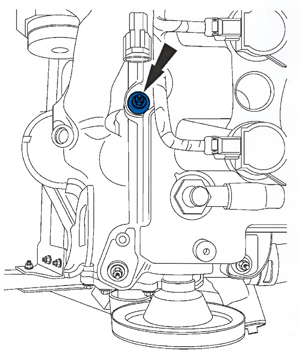
equipped with the 3.0L 4V Duratec engine with exhaust camshaft-driven water pumps.

Service Procedure
To diagnose, with the engine running and warm (normal operation temperature), use a mechanic’s stethoscope to determine if the ticking noise is coming from the left-hand exhaust camshaft at cylinder #6 (see Figure 1). If the ticking noise can be verified, refer to the following instructions.

For 2008 Escape and Mariner, check the date on the left-hand cam cover engine label. If the engine build date is 5/16/20007 or before, refer to the following to identify and resolve the engine ticking noise. For engines built after this date, this procedure does not apply; refer the Workshop Manual (WSM), Section 303-00.

For 2007 Fusion and Milan, check the date on the front cover label. If the engine build date is 5/9/2007 or before, refer to the following to identify and resolve the engine ticking noise. For engines built after this date, this procedure does not apply; refer the WSM, Section 303-00.

1. Remove the left-hand camshaft cover. Refer to WSM, Section 303-01 of the appropriate manual.

2. Rotate the engine clockwise until the cylinder #6 exhaust cam lobes are pointing up and the valves are fully closed.

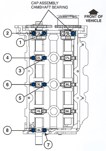
3. Remove all left-hand exhaust cam caps individually and reinstall them finger tight.

4. Torque bolts in sequence as shown in Figure 2, to 72 lbs.-in. (8 Nm) excluding cam cap #4L camshaft cap.

5. Using a screwdriver positioned on each side of the top of cam cap #4L (see Figure 3), apply hand pressure and shift cam cap #4L toward the exhaust side of the cylinder head.

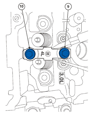
6. While holding cam cap #4L in the shifted position, torque fastener #9 (inboard) first, to 72 lbs.-in. (8 Nm), then torque fastener #10 (Figure 3).

7. Install the left-hand camshaft cover. Refer to the appropriate WSM, Section 303-01.

8. Fully warm the engine to verify the repair.

Technical service bulletin courtesy of Mitchell 1.

For more information on Mitchell 1 products and services, automotive professionals can log onto the company’s website at www.mitchell1.com.

You May Also Like

Wheel Bearing Shortcuts

When you’re installing a wheel speed sensor on a hub unit, never ever remove it from the original unit. Sponsored by Auto Value and Bumper to Bumper.

Hey, I got a great shortcut for you. If you're working on wheel hubs, if you have one where you're dealing with a harness for the wheel speed sensor that may be behind a fender liner, has all these horrible Christmas trees on it to get in and out from behind areas that you've never seen, well, you can just simply take the old out and then put it in the new and get rid of the new harness. Do not ever use the shortcut. It is a bad thing to do because you are destroying the calibrated air gap that was done at the factory, and this is very precise, done with computers. By removing the wheel speed sensor from one and putting it in another, you've just changed everything completely and you're gonna cause yourself a comeback. Do you wanna know why? Well, it's gonna cause an erratic wheel speed sensor code or issues with the air gap.

Monitor Water Quality When Servicing Coolant

The harder the water, the more likely the water pump is to develop a leak.

Rough Running GM Vehicle

This condition may be caused by an internal circuit board fault within the throttle body.

Diagnosing Intercooler Boost Trouble Code P0299

The criteria for setting the code is very basic.

Autel Energy Europe Releases MaxiCharger Launch Plan

Autel introduced the MaxiCharger Megawatt Charging System satellite launch plan at the Nordic EV Summit 2024.

Other Posts

Success Means Investing In More Than Equipment

Todd Baldridge measures success by how well his team benefits from being together.

Fenix Parts Completes Acquisition of Neal Auto Parts

Neal is an automotive recycler servicing the Central Illinois market with a population of approximately 1.3 million people.

Clarios to Supply High-Performance AGM Battery to Major OEM

It offers up to 80% reduction in CO2 emissions over traditional AGM batteries, in many cases, Clarios said.

FLO, GM Activate Plug and Charge for GM EV Drivers in Canada

FLO’s technology confirms identification, authorizes the charging session and activates billing without any additional action from the driver.