 It’s a familiar story, a DeLorean found with only 100 miles on the odometer. DeLorean owners and enthusiasts know to be wary, a car left sitting that long and havoc ensues with the sensitive fuel system of a 25-year-old DeLorean.
In fact, any car, left sitting for a lengthy period of time will eventually encounter fuel problems. One specific problem to note would be the need for a new fuel pump.
Cars left sitting, and even daily drivers, can fall victim to fuel pump failure. Over time, debris and contaminants build up in the fuel tank.
As the fuel pump does its job picking up and supplying fuel, it also picks up debris and contaminants.
Eventually those nasty little buggers cause the pump to seize, and replacement is the long-term, sensible solution.
 Indications or symptoms of a bad fuel pump can be vague, often presenting themselves as a whining car or one that won’t start.
Those two symptoms alone aren’t enough to make a determination; after all, they could just as easily be associated with a myriad of other possibilities.
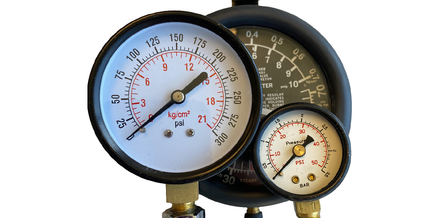
However, combine those with a sudden drop in fuel pressure and you’ve got your answer.
The best way to determine if this is, in fact, the problem is to run a fuel pressure test. If the needle doesn’t reach at least 5 kp, then you’re up for a pump replacement.
So, if it’s time for a DeLorean to get a new one, follow the steps below as they lead you through removal and installation, getting you back on the road to the future.
Before beginning, it is highly recommended that you have a DMC (Texas) Parts Manual handy as you perform this installation and removal.
 The illustrations in the parts manual, as well as the listed parts, will aide you in the installation.
Also, when it comes time to take apart the existing fuel pump assembly and save parts for use on the new fuel pump assembly the parts manual illustration numbers and part numbers will be used to help you identify these parts.
See Section 2-1-0 in the parts manual: Fuel and Emission Systems.
Parts to Save
All items, unless otherwise noted, are illustrated in Section 2-1-0 of the DMC (Texas) Parts Manual.
1. Support Ring (Illustration No. 46) P/N 101644
2. Steel Tube – Fuel Return (No. 66) P/N 105020
3. Fuel Pump Banjo Body (No. 50) P/N 106978 to VIN 10000 P/N 110594 from VIN 10001
4. Fuel Return Hose (No. 68) P/N 106286
5. Fuel Baffle (No. 78) P/N 110155
6. Retainer Spring (No. 73) P/N 108905
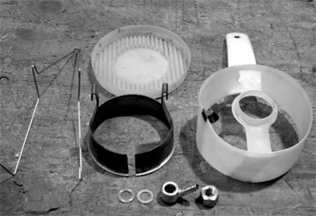
Note: Visually inspect each part you are saving.
 See Figure 1.
If any parts show extreme signs of wear such as rusting, cracking, swelling, bloating or other wear or damage discard them and replace with new parts. Over time, rubber that is constantly exposed to gasoline will break down and deteriorate. Though you may not realize it, this deterioration is released into the fuel tank and then returned to the fuel pump assembly, thereby negatively affecting the new filter and pump.
Every part removal and installation has an order of operations and the fuel pump installation is no exception. Before beginning the installation, gather the tools necessary to complete the job. The first step is to remove the old fuel pump; there will be a few parts you’ll need to save and re-use. After that comes the assembly of the new parts and re-used parts and finally the installation.
Fuel Pump Removal
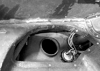
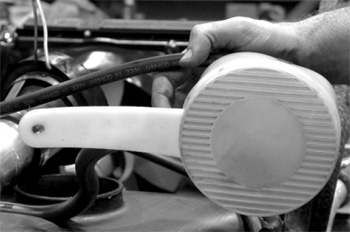
1. Start the removal process by accessing the area in which you will be working. To do so, you’ll need to remove the fuel pump access cover located underneath the spare tire in the luggage compartment. To remove the access cover, use your P2 Phillips head screwdriver.
See Figure 2 for an example of the access area.
Note: Before removing the old fuel pump, take note of the positioning of the fuel pump and lines. Notice how the exterior fuel lines twist and secure to the fir tree connectors. Also notice how the two-prong fuel pump harness connects to the main electrical harness.
 2. Using a utility knife, cut the return and feed lines. Take care; do not cut the fuel pump harness, as you will be re-using this part later. Also be aware that there may still be gasoline in these lines that could spurt or leak when the lines are cut.
After you’ve cut the lines you’ll have to strip the remaining pieces from their fittings using the utility knife, taking care not to damage the metal fuel lines. After the lines have been cut and stripped, gently pull upward on the fuel pump assembly to bring the fuel pump sealing ring up out off its location in the fuel tank.
3. Detach the two-prong fuel pump harness from its connection to the main electrical harness.
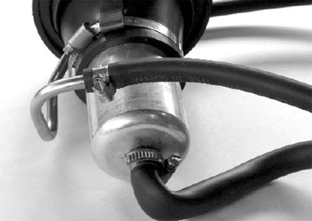
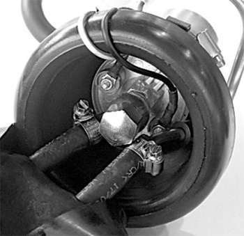
4. Use a 6 mm socket or a standard 1/4” screwdriver to remove the large hose clamp at the base of the sealing ring just above the base of the fuel pump.
5. Use the 6 mm socket or 1/4” standard screwdriver to remove the two hose clamps, one from the fuel supply and the other from the fuel return, both located at the base of the fuel pump, leaving the lines in the tank. Both hose clamps are illustrated in Figure 3.
6. You will need the 7” extension arm and a 10 mm deep socket to remove the nut and washer from the stud at the bottom of the fuel tank.
7. Reaching inside the fuel tank, gently remove the bottom of the fuel baffle by sliding it off of the main baffle tab. See Figure 4 for an example of the bottom of the baffle and the tab extending from the main baffle.
8. After removing the bottom of the baffle, grasp the main part of the baffle by the tab and gently pull through the fuel tank opening.
Fuel Pump Assembly
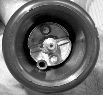
1. Start assembly by inserting the fuel pump into the fuel pump sealing ring. When doing so, make sure to twist the pump into the proper position, as shown in Figure 5.
The fuel line connections must be at an angle so as to not block the metal fuel return line when it is inserted into the sealing ring.
2. Insert the metal fuel return tube into the sealing ring. Make sure the rest of the return tube curves naturally around the body of the fuel pump.
3. Slide the support ring around the base of the fuel pump moving upward, guiding the notch over the metal return tube, until it fits securely underneath the lip of the sealing ring. After you have the support ring in place, secure it with the large hose clamp. The clamp should rest inside the loops of the support ring and tighten firmly around the sealing ring.
4. At the top of the fuel pump inside the sealing ring, attach the banjo fitting with one copper washer underneath and one on top. Tighten the banjo fitting with the domed nut provided in the kit.
5. Attach one flexible fuel line to the fuel return on the left and the other flexible fuel line to the feed on the right. Each fuel line requires a hose clamp at its base to secure it to the fuel pump.
 6. Attach the fuel pump harness to the new pump. Attach the white wire with the purple strip to the positive connection and the black wire with the purple strip to the negative connection as illustrated in Figure 6. Make sure the wires are turned toward the grooves on the outer lip of the sealing ring.
7. Using WD-40 or another spray lubricant, coat the holes on the seal cap as well as the two flexible fuel lines. Feed each line into its respective hole and slide the seal cap all the way down until it covers and secures over the sealing ring.
Before securing the seal cap over the sealing ring, make sure the harness wires are secure in
their grooves.
8. Attach your existing flexible fuel line to the steel fuel tub and secure it with a small hose clamp to ensure a good seal. Attach the other end of this line to the clamp on the side of the fuel baffle. This line creates a whirlpool effect inside the baffle when it is in operation.
9. Attach the curved flexible fuel pick-up line provided with the kit to the bottom of the fuel pump and secure it with a hose clamp as well. Insert the other end of the fuel pick-up line into the baffle through the hole located above the tab on the baffle, then attach the fuel pick-up filter and secure in place with a hose clamp.
10. Place the metal retaining spring over the top of the baffle.
Installation
1. Once the assembly is complete, grasp the baffle by the tab and gently push it through the fuel tank opening.
2. Gently pinch the bottom of the baffle in the same direction as the grooves, push it through the tank opening, slide over the baffle tab and secure to the bottom of the baffle.
3. Using an M6 stainless steel nut and washer, secure the baffle to the stud.
4. Once the baffle is secure, press down on the seal cap until the edge is flush with the fuel tank and secure with a large clamp.
5. Connect the fuel pump harness to the main electrical harness.
6. Twist and connect the fuel return and feed lines to the fir tree connectors inside the access area. Replace the access cover.
You have completed the installation.
Courtesy of DeLorean Motor Company.