 A Honda Civic owner may complain that the starter motor intermittently grinds while cranking the engine. The cause may be that the female terminal at the starter solenoid may have spread apart, causing a loss of current to the solenoid. To correct the condition, replace the female terminal at the starter solenoid.
Applicable Models:
• 2001-’05 Civic 2-door — All except CVI
• 2001-’05 Civic 4-door — All except Hybrid and GX
Parts Information:
Spade Receiver Terminal: P/N 07JAZ-001420A.
Tool Information:
Terminal Crimping Tool: T/N 07JAZ-001020A or Suitable Equivalent.
Diagnosis:
1. If applicable, make sure you have the anti-theft code for the audio system. Write down the customer’s audio unit presets.
2. Disconnect the negative cable from the battery, then disconnect the positive cable.
3. Remove the resonator using factory and/or industry standard-approved practices.
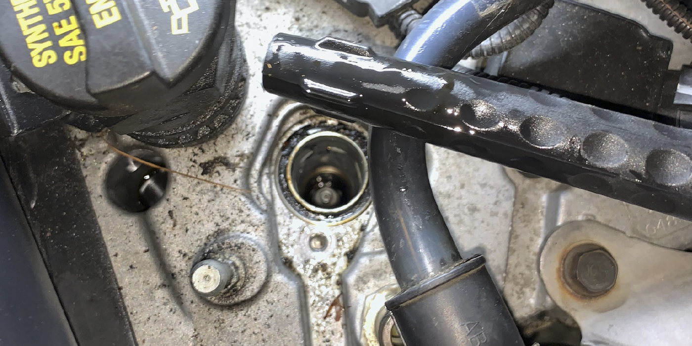
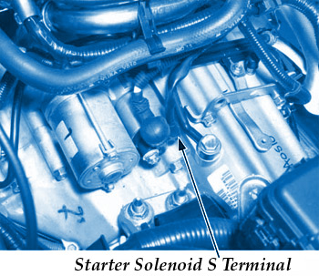
4. Disconnect the female terminal (BLK/WHT wire) from the S terminal of the starter solenoid (see Fig. 1).
Note: Auto transmission is shown; manual transmission is similar.
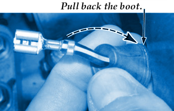
5. Pull the boot back from the female S terminal, and check the terminal for signs of arcing (see Fig. 2).
6. Check the male S terminal at the starter for signs of arcing.

7. If either terminal has signs of arcing, go to the Repair Procedure. If neither terminal has signs of arcing, continue your diagnosis using factory and/or industry standard-approved practices.
Repair Procedure:
 1. Cut off the female S terminal from the harness, making the cut as close to the terminal as possible (see Fig. 3).
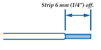
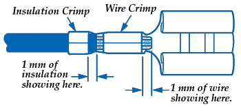
2. Strip 6 mm of insulation from the wire using the 2.0 slot on the crimping tool (see Fig. 4).
Note: Make sure no wire strands were removed when you stripped the insulation. If any were removed, cut the wire off even with the insulation, and strip it again.
3. Insert the wire into the new terminal so it fits as shown (see Fig. 5).
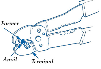
4. Using the 2.0 slot on the crimping tool, position the terminal in the tool slot with the solid portion of the terminal toward the anvil and the open section toward the former (see Fig. 6).
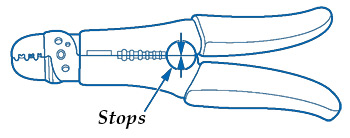
5. With the wire inserted in the new terminal as shown in step 3, crimp the wire in the terminal by squeezing the tool with both hands until the tool stops making contact (see Fig. 7).
6. Crimp the insulation by positioning the 5.5 slot on the tool over the insulation crimp section of the terminal and squeezing the tool with both hands until the tool stops make contact.
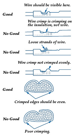
7. Inspect the quality of the wire crimp. If it has any of the “no good” crimps shown, cut it off and start over (see Fig. 8).
8. Clean the starter side of the S terminal as needed using a suitable electric contact cleaner and an electrical connector cleaning brush. Blow out any debris remaining on or around the terminal with compressed air.
9. Apply silicone dielectric grease to the female side of the S terminal, then carefully insert the terminal into the S terminal on the starter side.
10. Slide the boot completely over the S terminal.
11. Reconnect the positive battery cable, then reconnect the negative battery cable.
12. Enter the anti-theft code for the audio unit (if applicable), then enter the customer’s audio presets. Set the clock.
13. Confirm that the starter engages properly by starting the engine several times.
14. Perform the idle learn procedure:
• Make sure all electrical items (A/C, audio unit, defogger, lights, etc.) are off.
• Start the engine and let it warm up to its normal operating temperature (the cooling fans cycle twice).
• Let the engine idle (throttle closed and all electrical items off) for 10 minutes.
Written by By Ed Dorowski, ALLDATA editor, and Jeff Webster, ALLDATA Technical writer.