Rich Diegle
Automotive Editor
Some 2004-2005 Cadillac CTS-V owners may comment on rear wheel hop or rear suspension bounce under full throttle acceleration. This condition is primarily confined to hard acceleration from a standstill with wide open throttle, though it may be possible to induce if the customer attempts a wide open throttle or "Power-Shift" from 1st to 2nd gear.
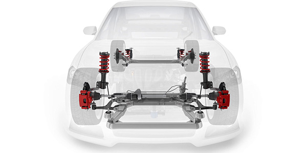
In the rear of the CTS-V, a sub-frame is mounted to the body structure at four rubber-isolated points. The manufacturer installed mounts to improve handling and damping of road shocks and bumps. The force of the suspension rapidly oscillating vertically (hopping) provides enough weight transfer (up and down) that these bushings may deflect or compress.
For customers who value very aggressive driving capabilities, a revised set of firmer rear sub-frame bushings are available that may provide an incremental improvement in reducing the tendency of the rear suspension to wheel hop. This improvement will further extend the handling capabilities of the CTS-V, but it will not entirely remove the possibility of wheel hop in all situations.
Service Procedure
Review safety procedures in ALLDATA Repair before beginning.
Use the following procedure to install the rear frame supplemental bushings.
1. Raise and suitably support the vehicle.
2. Remove the left and right rear tire assemblies. 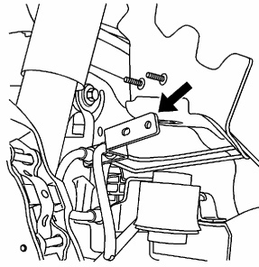 3. Support the right rear lower control arm with a stand.
4. Remove the lower shock absorber mounting bolt and gradually lower the stand until the right control arm is hanging.
5. Remove the stand and use it to support the left rear lower control arm.
6. Remove the lower shock absorber mounting bolt and gradually lower the stand until the control arm is hanging.
7. Remove the brake pipe mounting bracket from the right side wheel well area.
8. Remove the right and left side exhausts from the hangers nearest the rear fascia.
9. Install jacks and suitably support the rear frame.
10. Remove the four rear frame attachment bolts.
CAUTION: Only lower the rear frame enough to install the new bushings. The above steps include removal of components sufficient to lower the frame enough to complete this operation. Additional lowering of the frame
may cause stress or damage to other components.
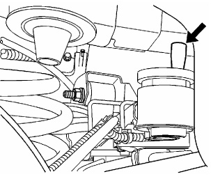
 11. The rear frame mounting points have reverse cone shaped locators as an integral part of the location. Lower the rear frame to obtain sufficient clearance to install the revised insulators.
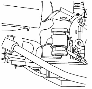
12. The new bushings are installed over the existing bushings by inserting them into the voids of the original bushings. The front and rear frame bushings are different diameters, but each matching half is the same and will only fit the proper locations. Install the new bushings to the frame mounts as shown in the illustration.
WARNING: When raising the frame back to the vehicle, you will need to guide the coil springs back to their original mounted location points. Raising the frame back to the vehicle underbody will re-tension the springs. Failure to properly locate the springs upon re-installation of the frame may cause personal injury or damage to the vehicle.
 13. Raise the frame making sure that the locating pegs are positioned properly and guide the frame to the correct position.
14. Install the rear frame bolts.
15. Remove the supports from the rear frame.
16. Support and slightly raise the left lower control arm to install the left shock absorber bolt to the lower control arm. Remove the support.
17. Support and slightly raise the right lower control arm to install the right shock absorber bolt to the lower control arm. Remove the support.
18. Install the left and right wheel and tire assembly.
19. Lower the vehicle.
Written by ALLDATA Senior Automotive Editor, Rich Diegle. Rich is an Advanced Engine Performance Certified, ASE Master Technician with an AA Degree in automotive technology and 23 years of dealership and independent shop experience.
For additional information, visit www.alldata.com.