 Ford:
Ford:
1996-’99 Taurus SHO
1998-2006 Crown Victoria, Mustang
2000 Taurus
2002-’05 Thunderbird
2003-’06 Focus
2004-’06 Taurus
2005-’06 Five Hundred, Freestyle
1997-2006 E-Series, Expedition, F-150
1999-2006 F-Super Duty
2000-’05 Excursion, F-53
2001-’06 Escape
2002-’05 Explorer
2005-’06 Escape Hybrid
Lincoln:
1997-’98 Mark VIII
1998-2002 Continental
1998-2006 Town Car
2000-’06 LS
1998-2006 Navigator
2002-’03 Blackwood
2003-’05 Aviator
Mercury:
1998-2006 Grand Marquis
2000 Sable
2004-’05 Sable
2005-’06 Montego
2002-’05 Mountaineer
2005-’06 Mariner
2006 Mariner Hybrid
Note: Follow this TSB procedure only if there are no specific misfire TSBs/SSMs released for the vehicle symptom being experienced.
Issue:
Approximately 50% of coil on plug (COP) coils returned for warranty do not have a problem.
Action:
The misfiring cylinder must be identified through Self-Test misfire codes or through WDS Power Balance.
Rule out base engine problems; rule out fuel problems; and then look at ignition problems (be sure to rule out coil primary circuit issues).
 Once the folllowing steps have been completed, and the issue is in the secondary part of the ignition system, the oscilloscope procedure outlined in this TSB can isolate the difference between a coil or spark plug problem.
Service Procedure:
The optional WDS COP Kit available through Rotunda will provide more accurate
diagnosis and help reduce replacement of non-defective parts. The Kit (418-F5528) can be purchased through 1-800-ROTUNDA.
The following material will detail the diagnostic steps on WDS to take the guesswork out of misfire diagnosis using the COP kit. The following procedure is for cylinder-specific misfires and not
random misfires. Random misfires have a different root cause and are not covered by this TSB.
 Misfire Definition:
A misfiring cylinder is lacking power relative to the other cylinders. The causes for a cylinder-specific misfire could be fuel, spark or mechanical problems.
Perform a thorough visual inspection. If no visible concerns are found, use the following WDS tools for
misfire diagnosis:
– Self-Test (Check for codes first);
– Power Balance (Identify the cylinder of concern);
– Relative Compression (Rule out a possible mechanical issue);
– Fuel (Make sure fuel injectors are not restricted);
– Ignition (Make sure spark plugs and coils are working properly); and
– Oscilloscope (Detailed signal analysis).
 If there is a self-test code identifying a particular cylinder, then you just need to determine if it is a fuel, ignition or even a mechanical problem. Proceed to Step 2 on page 54 after running Relative Compression to rule out any mechanical issues. If there is no self-test code and the customer concern is a miss, proceed to Step 1.
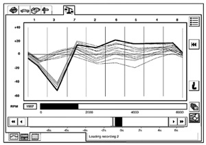
Step 1: (Select Toolbox Icon, then Powertrain, then Power Balance)
The cylinder-specific misfire has to be identified as shown in the example in Figure 1 in order to proceed with the remaining steps. If the miss does not occur at idle (in the bay), try to brake-torque the engine.
This extra loading should reproduce the miss in the bay. If the miss cannot be reproduced during brake torque, select Relative Compression under Powertrain on WDS before going on a road test to rule out mechanical problems.
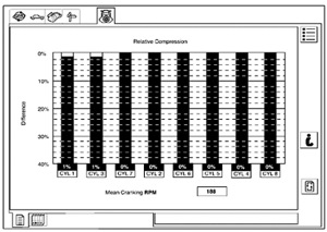
 If Relative Compression shows a problem then the base engine issue must be serviced. If Relative Compression results are good (see Figure 2), road-test under as many different driving conditions as possible until the miss occurs on Power Balance. Some misses may be very intermittent, so be patient and concentrate on steady-load conditions.
Once a cylinder dropout is identified, proceed to Step 2.
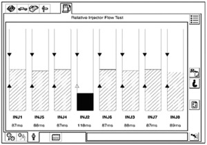
Step 2: (Select Toolbox Icon, then Powertrain, then Fuel System Test)
Run the Fuel System Test on WDS to determine if there may be a fuel problem. After completing the Fuel
Pressure/Leakdown Test, select Injector Flow to isolate a restricted injector as shown in Figure 3. If all of the injectors are within specification, proceed to Step 3.
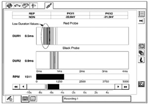
Step 3: (Select Toolbox Icon, then Powertrain, then Ignition System Test)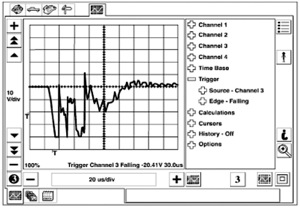
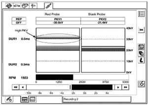
Run the Ignition System Test on WDS to determine if there is an ignition problem. Look at both duration (DUR) and kilovolts (KV), and look for values that standout from the rest as shown in Figure 4 and Figure 5.
Note: Live display has to average ignition values because there is too much data to display. Make a capture to view each engine event without averaging. This can be helpful when the problem is intermittent. If the miss is extremely intermittent and does not show up in ignition, proceed to step 4.
If either spark duration or peak KV on the red probe (suspect cylinder) are offset from the values displayed on the black probe (known-good cylinder), then the problem is in the ignition system.
Rule out coil primary circuit issues before proceeding to coil secondary issues such as the spark plug, coil boot or possibly the coil.
Use the WDS oscilloscope with the COP kit to determine if the issue is the coil or the spark plug.
Step 4: (Select Toolbox, then Oscilloscope)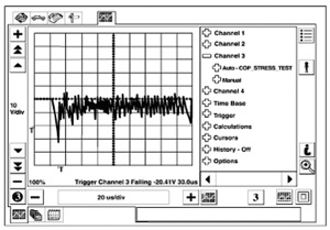
Warning: Secondary ignition voltages are very high. Keep hands and tools away from the end of the coil that supplies the spark.
Set-up:
With the engine off, pull the suspect coil from the cylinder well and turn it upside down so the coil cannot spark to any other surface. Wrap a clean shop cloth around the hard shell of the coil to help keep the coil propped up and stable.
Caution: The coil boot can be damaged if the coil sparks to another surface during this procedure.
Keep the coil connected to the harness and leave the WDS COP clip attached to the coil. Route the coil clip wire and cable away from the coil being tested, as well as other coils, to avoid noise interference.
Disconnect the injector of the cylinder being tested so raw fuel is not washing the cylinder. This is a stress test for the coil. The type of waveform displayed on the oscilloscope will show whether a coil or the plug is the problem, if all previous steps have been followed.
Keep hands and tools away from the end of the coil that supplies the spark.
COP Stress-Test Procedure:
Go to the Oscilloscope Tool and select Channel 3, then select Auto, then select COP_STRESS_TEST_RED.
This pre-configured setting will zoom-in on the peak firing of the coil being tested. Start the engine and be sure the coil is not sparking to any surface.
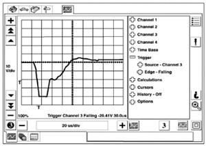
If the coil is sparking to other surfaces, turn off the engine immediately and readjust the coil so it cannot spark to any other surface. Restart the engine and touch the Red Man icon to start the oscilloscope. All settings are pre-configured and no adjustments are necessary. Compare the waveform you get with the examples provided in Figures 6, 7 and 8).
Figure 6 is a good waveform. If your waveform is similar to Figure 6, the coil is working correctly and the spark plug is suspect.
Figures 7 and 8 are examples of problem coils. Replace the coil if the waveform is similar to Figures 7 or 8. The coil is causing the misfire when the peak firing appears like those shown.
Notice the difference in the peak-firing signal when compared to the good peak signal in Figure 6. Figure 8 shows a more dramatic fault in the peak failure.
Most root causes of misfire issues can be identified quickly using the steps outlined above. Some misfire issues can be difficult making the oscilloscope an important part of your diagnostic toolbox.
Courtesy of Identifix.