By Larry Carley
Technical Editor
Instead of giving a simple rich/lean indication, wide ratio air/fuel sensors measure the “actual” air/fuel ratio. A WRAF sensor can measure mixtures that range from extremely rich to extremely lean (even straight air!). This ability allows the PCM to control fuel mixtures much more precisely, to handle much leaner fuel mixtures, to reduce emissions and to improve fuel economy compared to ordinary switching O2 sensors. WRAF sensors react much faster than ordinary O2 sensors, which allows them to monitor the fuel mixture from individual cylinders as each puff of exhaust blows by the sensor element. The PCM can then adjust the mixture for each cylinder individually to reduce emissions and optimize fuel economy.
Car makers also like the new WRAF sensors because they allow the use of thinner catalyst coatings (platinum, palladium and rhodium) inside the catalytic converter. With the soaring price of precious metals lately, this can add up to significant cost savings for a vehicle manufacturer that produces millions of vehicles a year.
WRAF Operations
WRAF sensors don’t generate a voltage signal like a common zirconia O2 sensor. An ordinary O2 sensor produces a voltage signal of 0.8 to 0.9 volts when the air/fuel mixture is rich, then drops to 0.3 volts or less when the air/fuel mixture goes lean. The transition is quick and abrupt, so the PCM has to keep track of the back and forth rich/lean transitions to estimate the average air/fuel mixture.
By comparison, a WRAF sensor produces a signal that corresponds to the exact air/fuel ratio. Engineers call this a “linear” output because it changes in a smooth, predictable fashion. If you compare the output graphs of an ordinary oxygen sensor versus a WRAF sensor, the differences are obvious.
 The ordinary O2 sensor signal voltage starts out high and remains high as long as the air/fuel mixture is rich. Then it drops suddenly when the mixture goes lean and stays low regardless of how much leaner the air/fuel mixture might become. The WRAF sensor signal starts out low and gradually increases its output as the air/fuel ratio gets progressively leaner. This allows the PCM to accurately monitor the exact air/fuel ratio, including extremely lean ratios (18:1 and higher) that are increasingly common on late-model ultra-low emission engines.
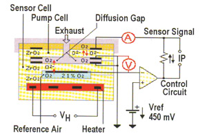
The WRAF sensor’s internal voltage output is converted by its built-in circuitry into a variable current signal that can travel in one of two directions (positive or negative). Think of it as a signal generator that can change polarity. The signal gradually increases in the positive direction when the air/fuel mixture becomes leaner.
At the “stoichiometric” or “lambda” point when the air/fuel mixture is perfectly balanced (14.7:1), the current flow stops and there is no current flow in either direction. When the air/fuel ratio becomes progressively richer, the current reverses course and flows in the negative direction.
Doing the Math
Depending on the vehicle application and capabilities of your scan tool, you may also see a lambda PID value displayed for the air/fuel ratio. Lambda is the Greek symbol used to represent the air/fuel ratio. At stoichiometric, lambda equals 1. Lean mixtures have a lambda value greater than 1, while rich mixtures have a lambda value less than one.
The lambda PID reading can be converted to a numeric air/fuel ratio for air and gasoline by multiplying the Lambda value times 14.7.
Example: If the lambda reading is 1.23, the air fuel ratio is actually 18:1 (1.23 x 14.7 = 18.08), which is a lean mixture.
The PCM sends a control reference voltage (typically 3.3 volts on Toyota applications, 2.6 volts on Bosch sensors) to the WRAF sensor through one pair of wires, and monitors the sensor’s output current through a second set of wires. The sensor’s output signal is then processed by the PCM, and can be read on a scan tool as the air/fuel ratio, a fuel trim value and/or a voltage value, depending on the application and the display capabilities of the scan tool. For applications that display a voltage value, anything less than the reference voltage indicate a rich air/fuel ratio, while voltages above the reference voltage indicates a lean air/fuel ratio. On some of the early Toyota OBD II applications, the PCM converts the WRAF sensor voltage to look like that of an ordinary oxygen sensor (this was done to comply with the display requirements of early OBD II regulations).
Sensing Problems
WRAF sensors are designed for a service life of up to 150,000 miles under normal driving conditions. But like ordinary O2 sensors, WRAF sensors are vulnerable to contamination and aging. They can become sluggish and slow to respond to changes in the air/fuel mixture as contaminants build up on the sensor element. Contaminants include phosphorus and zinc from motor oil, silicates from antifreeze, and even sulfur and other additives in gasoline.
Like ordinary O2 sensors, WRAF sensors can also be fooled by air leaks in the exhaust system (leaky exhaust manifold gaskets) or compression problems (such as leaky or burned exhaust valves) that allow unburned air to pass through the engine and enter the exhaust.
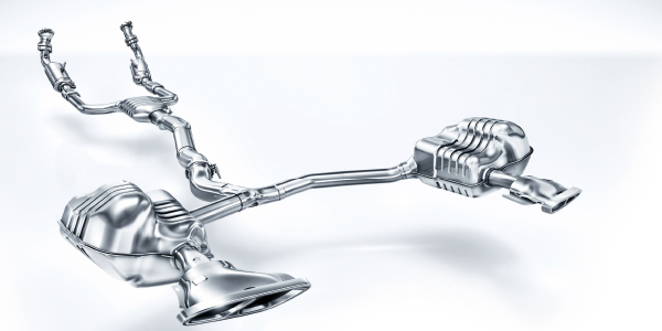
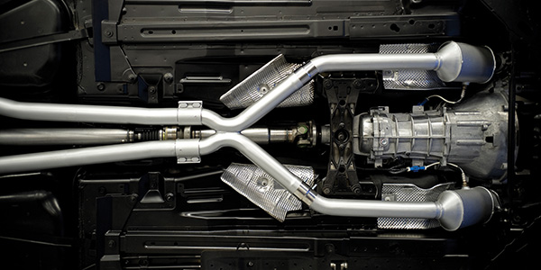
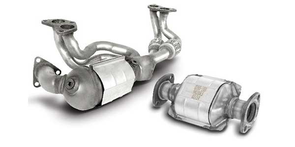
It’s important to make sure a bad WRAF sensor has been correctly diagnosed because the OEM list price on some of these sensors is several hundred dollars.
WRAF Diagnostics
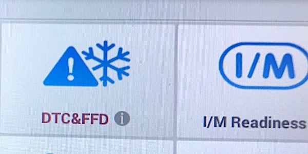
As a rule, the OBD II system will detect any problems that affect the operation of a WRAF sensor and set a DTC that corresponds to the type of fault. Generic OBD II codes that indicate a fault in the WRAF sensor heater circuit include: P0036, P0037, P0038, P0042, P0043, P0044, P0050, P0051, P0052, P0056, P0057, P0058, P0062, P0063 and P0064.
Codes that indicate a possible fault in the WRAF sensor itself include any code from P0130 to P0167. There may be additional OEM “enhanced” P1 codes that will vary depending on the year, make and model of the vehicle.
The symptoms of a bad WRAF sensor are essentially the same as those of a conventional oxygen sensor: An engine running rich, poor fuel economy and/or an emissions failure due to higher than normal levels of carbon monoxide (CO) in the exhaust.
Other factors that may affect the output of a WRAF sensor include bad wiring connections or a faulty heater circuit relay (if there are heater codes), or a wiring fault, leaky exhaust manifold gasket or leaky exhaust valves if there are sensor codes indicating a lean fuel condition (P0171 or P0174, for example).
To check the response of a WRAF sensor, plug a scan tool into the vehicle’s diagnostic connector, start the engine and create a momentary change in the air/fuel radio by snapping the throttle or feeding propane into the throttle body. Look for a response from the WRAF sensor. No change in the indicated air/fuel ratio, sensor voltage value or short-term fuel trim number would indicate a bad sensor that needs to be replaced.
Other scan tool PIDS to look at include the OBD II oxygen heater monitor status, OBD II oxygen sensor monitor status, loop status and coolant temperature. The status of the monitors will tell you if the OBD II system has run its self-checks on the sensor. The loop status will tell you if the PCM is using the WRAF sensor input to control the air/fuel ratio. If the system remains in open loop once the engine is warm, check for a possible faulty coolant sensor.
Another way to check the output of a WRAF sensor is to connect a digital voltmeter or graphing multimeter in series with the sensor’s voltage reference line (refer to a wiring diagram for the proper connection). Connect the black negative lead to the sensor end of the reference wire, and the red positive lead to the PCM end of the wire. The meter should then show an increase in voltage (above the reference voltage) if the air/fuel mixture is lean, or a drop in voltage (below the reference voltage) if the mixture is rich.
WRAF sensor output can also be observed on a digital storage oscilloscope by connecting one lead to the reference circuit and the other to the sensor control circuit. This will generate a waveform that changes with the air/fuel ratio. The scope can also be connected to the WRAF sensor heater wires to check the duty cycle of the heater circuit. You should see a square wave pattern and a decrease in the duty cycle as the engine warms up.