ent 5″/>
In the past, I’ve always hunted down parasitic draws with my multimeter set on the amperage scale in series with the battery cable, along with jumper leads to open and close the connection, so I could watch for the amperage drop. I also needed to know what a safe level was in order to see the actual draw (or lack of). Some techs use a dead-man switch attached to the battery post instead of jumper wires. For me, it’s whatever I have handy at the time, and time is money so the quicker I can get to the source of the problem, the better that is for my bottom line.
Sometimes, these draw tests can take hours to complete, depending on what module you’re looking at and the length of time it takes to power down (Sleep Mode). I find it not only awkward, but a little confusing, to have all of these devices on an adjacent worktable or balancing precariously on the edge of the fender. It wouldn’t be the first time I’ve knocked something over and had to set it up all over again. I want to get in there, find out what’s wrong, inform the customer, and get the job done. 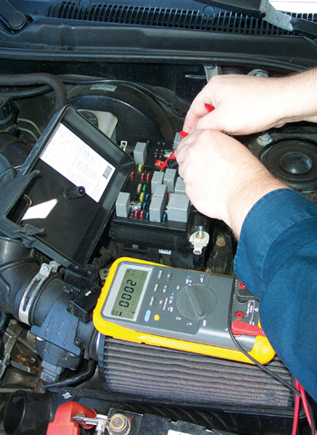
And, it almost never fails that I’m the guy who will pick up the meter and find the amp fuse is blown because I never bothered to switch the leads back over before putting the meter away. I’m usually aware of this only after I’ve got everything all set up and ready to start my amperage draw tests. When this happens, it’s time to slow down, take the meter apart, remember where I hid the extra fuses so I wouldn’t lose them and then have to start over all again.
The other thing you need to do to properly perform the draw test is the correct values for each system’s parasitic draw. I find it a lot easier to watch the meter values dropping off to their sleep mode when I have a pretty good idea as to which module it is. But this requires me to stand over the meter and be ready to pull fuses (if needed) at a moment’s notice, all of which is time consuming, involves lots of connections that have to be working correctly, as well as a lot of patience on my part. With too many variables, something can, and usually does, go wrong. When it does, I think there has to be a better way.
I really would like to have a way to at least isolate the offending circuit quickly, efficiently and accurately without all these hassles. How about a way I can see the draw without disconnecting anything? No pulling fuses, no need for a dead-man switch and no need for that temperamental amp meter hook-up, which we all (me included) forget to switch back when we check voltage the next time we need the meter. Well, there is…
 Before parasitic draw testing, it was the tried-and-true old test light method between the battery post and cable. While it wasn’t precise as far as voltage or amperage, it was accurate enough and it got the job done. If the test light was even partially lit up, there was a draw. I never worried about the actual amount; it wasn’t as important as the “where is it.” So, how about a way to locate these draws in a late-model car and not worry so much about the exact values; just find the problem and leave all that technical mumbo-jumbo aside. There is a way, and all it takes is your voltmeter.
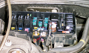
Start with a good multimeter (DVOM) with an mV scale (millivolts) and a couple of good test leads with sharp, pointed ends. Put the meter on the millivolt scale and your test leads on the two test points on the back of the suspected fuse, and then measure the voltage. Yes, put the negative lead from your meter on one of the fuse test terminals and the positive lead on the other. (On some fuses, these little test spots on top of the fuses are quite small, so this is where the sharpened points of the test leads will help out.)
A good practice session for this method is to try this on a car that is working. Find the dome light fuse and watch the meter. If there is no current flow across the fuse, the meter will read a flat zero. If there is a current flow in the fuse, you will measure a steady voltage drop of some sort from the time the door is opened to the time the dome light finally goes off. It doesn’t matter what the voltage is, just that it is there.
The reason this works is that all circuits have some resistance in them. This resistance to current flow causes a minute change in the voltage readings from the source to the load itself. Current flow also creates heat, heat increases resistance and current flow through this resistance is seen on your meter as a voltage drop. Any voltage measured across the fuse then indicates some current flow.
If you get a small, fluctuating voltage, you’re probably not on the fuse test points. This is where those sharp test probes really help out again. There should be either no voltage at all, or some sustained voltage level that will be constant. Just like any other testing method, practice makes perfect, and trying this out on a car with no problems is a good way to see how this whole thing works.
Some mV meters are so sensitive that you may even see a fluctuating voltage reading as you get close to the fuse, or in the air around the circuit when it’s not hooked to anything. If so, try touching the two leads together before you hook it up. If all is well, the meter should read zero voltage at that point.
I prefer this method to the amp meter testing method. During the process, I’m not disconnecting anything, I’m still looking at a voltage drop (not amperage) and I’m less likely to screw up another amp fuse in my meter. I’ve even had success with this by starting at the MAXI fuse, then following the wiring diagram to break it down even further until I found the source of the draw.
The only time I start pulling fuses is after I’ve gotten the draw isolated to one section of the wiring diagram or fuse box. I’m not concerned so much with accurate values or amperage loads, just where the draw is originating. The fact that I’m seeing voltage on the meter in a circuit that shouldn’t have any current movement is enough information for me to suspect that this circuit is the culprit.
This is as close to using the old test light method as I’ve ever found. Mind you, the reason the test light worked at all is for the same reasons this test works. The presence of any load requires both positive and negative to create current flow. Thus, the reason the test light lit at all. Give it a try; I’m sure you’ll be impressed. Good hunting!
————————————————————————-