Mass airflow sensors or, more technically, “airflow sensors,” are an integral part of modern import engine management systems. In addition to providing an exact measurement of airflow into the engine, airflow sensor inputs can be used to measure intake air temperature, provide an emergency shut-off for the fuel pump and provide a load-sensing input to the powertrain control module (PCM) to help control the shift points and shift quality of an automatic transmission.
Until airflow sensors were popularly introduced, engine management systems used the throttle sensor, intake air temperature, engine speed and intake manifold absolute pressure (MAP) to calculate (rather than directly measure) the volume of air flowing into an engine. These systems were called “speed density” systems.
In the case of engine management systems using an airflow sensor, airflow is converted directly into a voltage or frequency signal that’s sent to the PCM. The direct measurement provided by an airflow sensor reduces fuel calculation errors caused by the miscalibration or degradation of the throttle, intake air and manifold absolute pressure sensors.
Vane-Type Airflow Sensors
Many 1980s and early ‘90s vintage imports use an expensive, but very reliable vane-type airflow sensor. Vane-type sensors generally require little maintenance, other than to ensure that the assembly is clean and that the vane quickly responds to air flow.
The internal components include a jeweled movement and return spring for the air vane and a potentiometer that indicates vane position. A by-pass air passage is used for measuring idle air and a factory-adjusted idle mixture screw might also be included to trim idle-speed air/fuel ratios. Most vane airflow meters also measure intake air temperature and include a switch that acts as a safety shut-off for the vehicle’s electric fuel pump. The diagnostics are straightforward, requiring the measuring of specified electrical input and output values with a digital volt-ohm meter as the vane opens and swings through its range of travel.
Karman Vortex Sensors
Some import vehicles use a Karmen Vortex airflow meter to supply an airflow input to the engine management system. Although Karmen Vortex airflow sensors are relatively uncommon, it’s important to recognize that they measure airflow by creating a swirling effect or vortex in the airflow stream. Airflow is measured by directing the airflow against a metal foil mirror that’s illuminated by a light-emitting diode (LED). Changes in the vortex of the airflow as it passes over the mirror causes variations in light reflected from the mirror. These variations in reflected light are translated into a frequency indicating the amount of airflow into the engine.
Hot-Wire Sensors
Hot-wire sensors, which are the most commonly used in current automotive applications, operate on the principle of electrical resistance in a heated wire changing in response to the cooling effects of air flowing past the wire. The hot-wire sensor also contains a thermistor that measures the temperature of the incoming air.
In a Toyota application, for example, the temperature of the hot wire is maintained at a constant value in relation to the temperature indicated by the thermistor in the sensor’s electronic circuit. These changes of current flow in the hot wire are translated by the MAF sensor electronics into a variable voltage or frequency signal that indicates to the PCM the amount of air flowing into the engine. The PCM then calculates an air-to-fuel ratio that corresponds with engine speed and load. The hot-wire sensor may also contain a separate intake air temperature sensor that provides an independent air temperature input to the PCM.
Airflow Sensors and Air Filters
Most airflow sensors fail because inferior replacement air filters are installed or because the integrity of the air filter box is compromised during service. Although it’s relatively rare, some cheaply made air filters shed paper particles into the air stream, which accumulate on the hot wire. These particles insulate the hot wire from the cooling effects of the air stream, which causes the airflow sensor to underestimate airflow at highway speeds.
Other cheaply-made air filters tend to leak dirt at perforations in their pleats and allow dirt and other debris to accumulate on the hot wire. In other cases, damaged seals on the air box allow air-borne dirt to flow around the air filter into the airflow sensor. If the air filter box is damaged, new assemblies are available from dealership parts and, in some applications, from aftermarket sources.
More controversial are the use of oil-impregnated performance filters on air intake systems. Some automakers will automatically void a new-vehicle warranty when one of these systems is installed. In other cases, less experienced techs over-oil the filter media, which causes oil to enter the air stream and accumulate on the airflow sensing elements. Many professional technicians feel that this accumulation of oil will seriously degrade the sensor’s performance.
 On the other side of the issue, manufacturers of oil-impregnated filters claim to have documented research showing that their brand-name oil won’t affect the accuracy of a hot-wire airflow sensor. In light of the above information, whether to install an oil-impregnated air filter or not amounts to a judgment call on the part of the vehicle owner, technician and shop management.
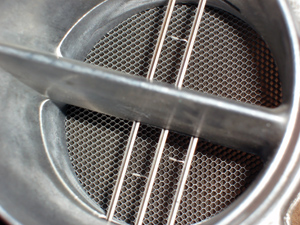
Another aspect of air filter performance is that air turbulence caused by modifying the intake air system can affect the accuracy of any hot-wire sensor. See Photo 1.
Because the air filter and air filter housing are designed to reduce airflow turbulence, modifying the intake air assembly always introduces the possibility that airflow sensor performance might be impaired.
Diagnostic Summary
Because hot-wire sensors are the most common, we’ll concentrate on summarizing conditions and pattern failures that affect hot-wire performance. Depending upon the sensor’s design and the software written into the PCM, a defective airflow sensor may or may not set a diagnostic trouble code (DTC) in the PCM’s diagnostic memory.
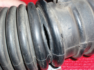 To illustrate, a no-code stalling complaint can be caused by a leak in the air duct tube connecting the airflow sensor to the throttle body. See Photo 2.
In most cases, the clamps holding the duct have been left loose following a previous service. In other cases, a crack will form in the accordion-style pleats of the duct that opens in response to engine torque. In either case, allowing “false air” to leak into the air stream causes airflow to drop nearly to zero through the airflow sensor. The PCM causes the stalling complaint by reducing fuel flow into the engine. Most stalling complaints caused by faulty ducting show up when the torque thrust of the engine is reversed as the transmission is shifted between forward and reverse gears.
No-code performance airflow sensor failures can be diagnosed on most airflow sensors by monitoring output voltage or frequency at idle to see if it meets specifications. Yet, some imports specify a grams-per-second value at specific engine speeds to determine the accuracy of the airflow sensor. Other imports use the airflow sensor to calculate barometric pressure. The accuracy of the barometric pressure calculation may indicate the overall accuracy of the airflow sensor itself.
Generic or SAE “P-zero” DTC issues are relatively easy to diagnose because the codes themselves describe the nature of the malfunction. A P0102, for example, indicates that the indicated airflow through the MAF is lower than that estimated by the PCM. A P0104 indicates that the signal from the MAF has become intermittent. One case in my recent memory includes a P0104 being caused by a loose connector pin in the MAF sensor receptacle.
In some applications, the PCM operates in a default mode when the airflow sensor is disconnected. If a poorly running engine suddenly springs to life when the airflow sensor is disconnected, the fault might lie with the airflow sensor.
Cleaning Mass Airflow Sensors
A dirty mass airflow sensor generally over-estimates intake air at low engine speeds and under-estimates intake air at highway speeds. In most cases, a P0171 (system too lean, bank 1) and a P0174 (system too lean, bank 2) indicate a dirty mass airflow sensor under-estimating airflow at highway speeds.
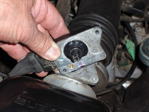 The sensor hot wire and thermistor can be cleaned using an aerosol-type mass airflow cleaning solution or a high-grade electric contact cleaner. A small artist’s paintbrush saturated with cleaner can be used to gently remove accumulated dirt and oil. Remember that harsh solvents like aerosol carburetor cleaner will ruin the mass air flow sensor. See Photo 3.
Many techs quite justifiably feel that cleaning a sensor won’t restore the sensor to 100 percent accuracy and recommend replacement instead. This is an entirely valid position in most cases. Much depends upon customer expectations and the standards of performance that the vehicle must meet. In any case, remember that a clean, well-maintained air intake system and airflow sensor are vital to good engine performance.