Tech Feature: Ignition Coil Diagnostics – UnderhoodService

Tech Feature: Ignition Coil Diagnostics

Import Specialist Gary Goms says there are a variety of opinions about how to test ignition coils and ignition systems. The most basic method is measuring a coil's primary and secondary resistance. If a coil doesn't meet the manufacturer's specifications, it should be considered defective. But meeting primary and secondary resistance specifications on the bench is no guarantee that the coil will perform correctly under extreme heat and load.

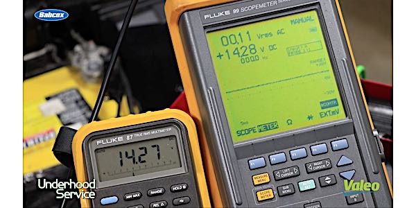
cuits can be a non-current-limiting design, which creates a pointed current ramp waveform. The ICM or PCM primary circuits can also be a current-limiting design that creates a “flat-top” waveform indicating that the primary current is being limited to predetermined values. See Photo 5.

Photo 5: This current ramp represents current flow through a coil-on-plug configuration. Notice that the current is about 4.4 amperes and is non-limited.

Access to the primary circuit can most often be obtained through the “ignition” fuse in the vehicle fuse box or directly at the primary ignition wiring harness leading to the ignition coils. In many cases, all of the system’s ignition coils are powered by a single wire, which simplifies attaching an inductive current probe. In COP ignitions with no other access, a set of jumper wires can be used to attach an inductive current probe. See Photo 6.

Photo 6: Access for an inductive probe can be attained on some COP ignitions by installing jumper wires between the coil connector and coil.

If the coil driver in the PCM is ruined or if an ICM fails, it’s always good procedure to check the current ramp on the ignition coil. Remember that most ignition coils shouldn’t draw more than eight amperes. If in doubt, compare amperage draw with a similar known-good system. If a coil is drawing excessive amperage, the primary circuit might be shorted which, in turn, might ruin the new PCM or ICM. If you’re in doubt about the integrity of any ignition coil, it’s better to replace with new than to risk a costly comeback.


You May Also Like

Ford Adaptive Cruise Control Alignment Process

Follow these steps for proper horizontal alignment of the cruise control module radar sensor.

• 2010-2017 Taurus, Explorer, Edge, Flex, Fusion, MKS, MKX, MKT, MKZ

• 2015-2017 F150, Mustang, and MKC 

• 2017 Super Duty, Escape, and Continental

This is information on setting up and completion steps for proper horizontal alignment of the cruise control module (C-CM) radar sensor.

Chrysler’s Totally Integrated Power Module Simplifies Circuits

The symptoms of a failing TIPM can vary depending on the vehicle. Check out your options for this repair.

Trakmotive Tech Tip: Window Regulator Installation

Here are eight tips to make your next window regulator replacement easier.

Multi-Spark Ignition Systems

You may have seen the stories about plasma or laser ignition systems that promise to give new life to the internal combustion engine. But while these ignition systems have yet to make it to market the latest ignition innovation still uses a coil and spark plug.

VIDEO: How Modules Manage Alternator Power

Andrew Markel discusses power flow through the electrical system on a vehicle, and how the modules help provide the right amount of power to different components. Sponsored by Valeo.

Other Posts

Caring For AGM And Flooded Car Batteries

Faulty battery cables, if loose, corroded, or damaged, can lead to power drainage.

Power Window Regulator and Motor Service

Power windows are great as long as they roll up and down when commanded to do so.

Battery Charging and Diagnostics

Here are six tips to use when diagnosing a vehicle with a dead battery. 

Power Window Regulator Replacement

Blindly replacing a window regulator and motor assembly may not solve a customer’s problem.