08 and european.”/>
Next, I entered Chrysler’s actuator test mode (ATM), which is a bi-directional feature used to activate or “buzz” the fuel pump, fuel injectors, ignition coils and other engine management system components. All of items on the ATM list activated correctly with the exception of the three waste-spark ignition coils. I couldn’t get spark from any of the front engine bank spark plug wires by activating the coils.
The primary ignition coil circuit on a 1996 3.3L Chrysler product is fairly simple. Battery voltage is supplied to the ignition coil primary circuits by the auto shut-down (ASD) relay when the PCM activates the ASD during cranking or running or during an ATM test. The PCM creates a spark by using a coil driver to ground the primary circuit to saturate the coil’s primary windings and then by breaking the coil primary circuit to create a high-voltage spark in the secondary circuit.
Because I had battery voltage at the B+ and B- primary coil terminals, it was easy to assume that either the CKP wasn’t signaling the PCM to ground the ignition coil primary circuits or the PCM itself wasn’t grounding the coils.
Because the PCM had been replaced at least three times with no result, I used the Module Identification feature of my aftermarket scan tool to verify that the vehicle had the correct PCM installed.
According to the scan tool’s Module Identification mode, the module was designed for “a 1997 Dodge 3.0L engine.” The fact that the PCM was designed for a 3.0L engine using a distributor-type ignition as opposed to a PCM designed for a 3.3L engine using a distributorless ignition did, indeed, explain why the engine had a spark-related cranking, no-start complaint. Oddly enough, the PCM’s data stream showed the camshaft and crankshaft sensors working perfectly, even though the PCM was a mismatch for a distributor-type and distributorless ignition.
Because the original computer had been returned for its core charge and because the 3.3L cores are becoming increasingly rare, the Dodge Caravan is now waiting for another rebuildable core. But the point remains that what first appeared to be an incredibly difficult diagnostic dilemma was solved relatively quickly and easily by using an aftermarket scan tool to determine that the last replacement PCM didn’t match the application.
Aftermarket Scan Tools
While many master technicians are now using original equipment (OE) scan tools to diagnose modern onboard electronics, suffice it to say that most professional-grade aftermarket scan tools still have the diagnostic capacity needed to solve the majority of electronics failures passing through an average independent repair shop. In brief, aftermarket scan tool manufacturers condense information supplied to them by OE tool manufacturers into menus designed to address the most common failures occurring in the most common vehicle platforms. The depth of coverage and diagnostic capability varies according to the vehicle application and the information-handling capacity of the scan tool itself.
Many aftermarket manufacturers also enhance the diagnostic capability of their scan tools by including technical hotline information, empirical or anecdotal information, engine testing and adjustment specifications, and OE technical service bulletins into their databases. When choosing an aftermarket scan tool, keep in mind that many are specifically designed for the domestic, European or Asian markets. Some, for example, concentrate on Mode $06 diagnostic information, while others concentrate on building a user-friendly format or extensive diagnostic database into their scan tools. Although most aftermarket scan tools are still produced in self-contained, updatable platforms, others are produced as PC-based software systems with cords and adapters needed to interface with vehicle data link connectors (DLCs).
Vehicle Identification
Because aftermarket scan tools have such a diversity of platforms and formats, I’ll use a Snap-on Solus Pro scan tool to illustrate the following installments of “Getting The Most Data From Your Aftermarket Scan Tool” in the most cohesive manner possible.
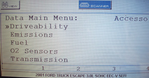
In general, the first menu displayed on an aftermarket scan tool has to do with correctly identifying the vehicle. When entering the “Global OBD II” or “generic” menu, keep in mind that it isn’t necessary to enter the Vehicle Identification Number (VIN). If Global OBD II is used, remember that the Global or generic diagnostic system is universally adapted for diagnosing emissions-related failures in all makes and models of vehicles and therefore does not have the overall diagnostic capability of the enhanced or “OE-style” diagnostic mode. Nevertheless, the Global OBD II mode may display freeze-frame and other data that may not be included in the scan tool’s enhanced mode.
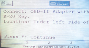
When entering the “enhanced” or “OE” diagnostic mode, the VIN must be entered manually unless, of course, the scan tool automatically enters the VIN. If the vehicle’s VIN has been previously entered into the scan tool, the application may be found in the “existing” or “previous” vehicle menu. After the VIN is entered, the next menu might ask the vehicle’s gross weight or if the vehicle is equipped with an air pump, manual or automatic transmission, or air conditioning. Last, the menu might specify a “personality key” or cable insert that adapts the scan tool cable to the vehicle’s OBD II diagnostic connector.
Module Communications
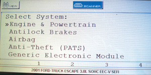
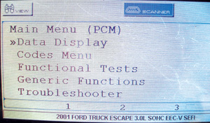
Because most current domestic vehicle models have at least four onboard modules (PCM, ABS, air bag, anti-theft, etc.) make sure the scan tool will communicate with each module before proceeding with a diagnosis.
Although aftermarket scan tool manufacturers are increasing their capacity to communicate with body control modules, keep in mind that because a module isn’t listed on the menu of an aftermarket scan tool doesn’t mean the module doesn’t exist. It simply means that the aftermarket scan tool won’t communicate with the module.
If you’re in doubt, attempt communicating by using another brand of aftermarket scan tool. In still other cases, the adapter key or insert must be changed before the scan tool will communicate with a specific module. Last, always poll each module for any diagnostic trouble codes. In some cases, these codes may influence the course of your diagnostic strategy.
When reviewing diagnostic trouble codes, remember that “P” is the prefix for powertrain codes, “B” is for body control codes, “C” is for chassis-related codes like ABS, and “U” is for network or data link communications codes.
To further illustrate, the zero following the “P” in a P0122 DTC indicates a “global,” “generic” or “SAE” DTC. If the “P” is followed by a “1” (ex. P1122) the DTC is a manufacturer-specific or enhanced code that may have a vehicle-specific definition. The second digit, number “1,” indicates the system (fuel/ air metering) and the third digit indicates the component and the type of failure being experienced (Throttle Position Sensor Circuit Low Voltage).
Serial Data Screens
The term “serial data” refers to a data stream being composed of a series of data bits, with each bit representing a specific type of data. Because of its structure, a serial data stream doesn’t instantly report a change in a specific value. Instead, we have to wait until the data stream updates itself before we can see the new data.
Because each line on a serial data screen must be continually updated, modern scan tools increase the update rate reducing the number of data lines per screen by dividing the data up into smaller screens. If, in the following photo, the O2 sensor screen is selected, the reduced number of data lines will permit faster numerical updates on oxygen sensor data.
Module Identification
In my opening case study, I mentioned the importance of identifying the module before beginning a diagnosis. On the Solus Pro scan tool, the module calibration numbers and VIN can be accessed through the main menu under “generic functions.”
Practice, Practice, Practice
Because there are literally thousands of scan tool menu formats in the current marketplace, it’s important for you, the technician, to get the most from your aftermarket scan tool by navigating through the menus. You’ll find that auto manufacturers may change their formats with each new vehicle introduction, and you might subsequently see considerable differences in menu formats and operational features from model year to model year.
In the next installment, we’ll look at how to use features like movie record, data graphing and other components of the modern aftermarket scan tool to diagnose no-code, random and intermittent component failures in modern engine management systems. Until then, spend a few extra minutes each day navigating your aftermarket scan tool. The reward will be increased diagnostic accuracy and reduced comebacks on diagnostic repairs.
NOTE: For Part II of Gary’s article, click here: https://www.underhoodservice.com/Article/68368/acquiring_data_on__scan_tools_part_ii.aspx