By Steve Miele, Ford Accelerated Credential Training (FACT) instructor,
Universal Technical Institute
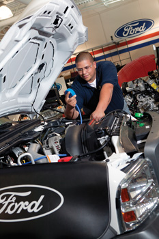 To diagnose and repair Ford exhaust gas recirculation (EGR) systems properly, it is important to understand how they work and what is unique to the product line.
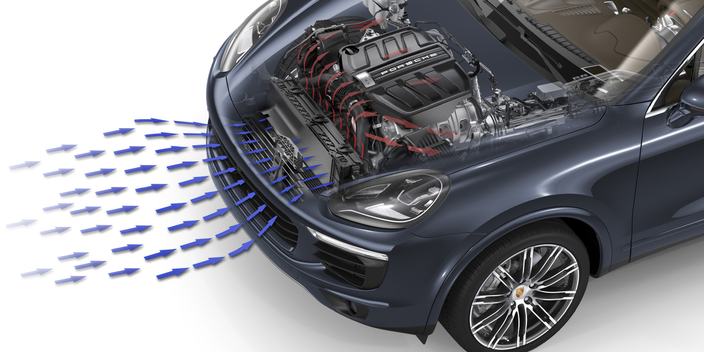
Ford EGR systems are designed to reduce smog-causing nitrous oxides (NOx) by recirculating a portion of the exhaust gases from each cylinder of the engine back into the intake manifold. This process lowers the combustion temperature to under 2,500° F, above which NOx gases are formed, hurting both the environment and a vehicle’s performance.
Typically, the Ford EGR system doesn’t require regular maintenance, but a valve that is clogged or sticks could result with the check engine light turning on, decrease in gas mileage, a vehicle that idles roughly or fails the next emissions test. Then what?
Ford EGR Systems
Late-model EGR systems are a differential pressure feedback system (DPFE) regulated by a power control module (PCM). The system is composed of a DPFE sensor, EGR vacuum regulator solenoid, EGR valve and assorted hoses.
The EGR valve is interposed between the engine exhaust and intake manifold. EGR flow is controlled by the engine’s computer, which opens and closes the EGR valve as needed.
When the system is functioning correctly, it precisely controls the flow of recirculated exhaust and helps reduce detonation under certain driving conditions by using its valve to control the flow of exhaust gases into the intake manifold. Since exhaust gases are inert when introduced into the cylinders, oxygen is displaced and causes the PCM to reduce fuel-limiting combustion temperatures. The gases also absorb heat.
Ford uses both vacuum-actuated and electrical EGR systems to recirculate exhaust gases. Ford’s vacuum-actuated EGR systems are the most common and work with the majority of gas engine applications. The electrical EGR systems are used in some four-cylinder and Ford diesel-powered vehicles.
Both these systems use an EGR vacuum regulator (EGRVR) duty-cycle solenoid to apply vacuum to the valve and a DPFE to monitor the flow rate.
There is a vacuum line coming off the intake manifold to the EGRVR actuator, an electric device controlled by the PCM that regulates how much vacuum is necessary. From there, another hose connects to the EGR valve, allowing exhaust gases to be pulled from the exhaust manifold, past the DPFE tubes, then back into the intake manifold.
The DPFE registers the amount of pressure differential across the orifice and tells the PCM how much exhaust gas is flowing through the EGR system. The PCM uses this report to control the actuator.
System Designs
The two Ford vacuum-actuated EGR systems are as follows:
• Differential pressure feedback (DPFE) EGR system — The orifice is located in the EGR tube.
• Electronic system module (ESM)EGR system — The orifice is incorporated into the EGR valve gasket.
The two Ford electric EGR systems include the following:
• Stepper motor valve — A temperature manifold absolute pressure (TMAP) sensor is used to monitor flow rate. This is used in some four-cylinder Fords.
• Duty-cycle solenoid valve — The EGR position sensor and the intake air temperature sensors (IAT 1 and IAT 2) are used to monitor the flow rate. This is seen in Ford diesel vehicles.
 Unique to Ford
The DPFE sensor is unique to Ford because it actually measures the flow of the exhaust gases. It is a pressure transducer that measures the pressure differential across an orifice in the EGR tube that runs from the exhaust manifold to the EGR value. This is an extremely accurate way to measure the actual flow of the exhaust gases. Instead of a calculated or inferred value, it is a measured value. The DPFE sensor used in the ESM system measures the exhaust side pressure, and the MAP portion of the sensor measures intake manifold side pressures. The ESM system incorporates the EGR valve, EVR solenoid and the DPFE/MAP sensor into one unit.
Diagnosing Problems
Potential problems could involve the flow of gases — when there is either not enough or too much in the system. Restricted flow can result in high NOx emissions and detonation (engine knock or ping) under certain driving conditions. Too much gas flow can result in rough idle stalling, as well as surging.
EGR valve problems can range from inoperative to sticking valves. There can also be PCM input or circuit issues. Sometimes the DPFE sensor becomes dysfunctional due to heat and moisture in the exhaust. The EVR solenoid vent or vent filter can become clogged, causing excessive EGR flow. Other problems can occur due to a blockage in the EGR passages due to carbon buildup.
The diagnostics associated with any of these potential problems should cover the symptom, system, its components and cause. Determining why the problem happened is perhaps the most important part of any diagnosis in order to minimize the possibility of any repeat failures. If EGR problems are ignored or not diagnosed correctly, the result can be high NOx emissions into the environment.
Engines that do not have detonation sensors to adjust the timing could have excessive detonation problems, possibly resulting in engine damage.
It may seem very basic when identifying the symptoms for EGR system failure, but always verify the concern and perform a visual inspection.
A “flow at idle test” is an excellent way to determine if the EGR system is the cause of a rough idle or stalling concern.
This test compares the DPFE Parameter Identification (PID) value — key-on-engine-off (KOEO) and key-on-engine-running (KOER) at idle. Both values should be the same.
More variation than 0.15 volts indicates EGR flow at idle. It is always important to reset any codes that may have been changed during testing.
There are a number of component tests to diagnose issues in the DPFE sensor, EGR valve control solenoid and the EGR value. These tests involve having access to a number of tools.
You may need a digital volt/ohm meter, hand vacuum pumps, test probes, scanners, appropriate test procedures and wiring diagrams.
The total replacement of an EGR component is generally an easy repair. On the other hand, carbon-filled, restricted or clogged intake passages along with wiring problems can take much more time. A trained technician can do both expeditiously.
 About the Author
STEVE MIELE began his career in automotive repair working at his uncle’s repair shop while finishing high school. He attended college and worked full-time as an automotive technician. In 1982, Miele opened his own independent repair shop. In 1998, he sold his interest in the business and began teaching at Universal Technical Institute’s (UTI) Avondale, AZ, campus, where he continues to train students to become automotive technicians. He joined the Ford Accelerated Credential Training (FACT) program at UTI Avondale in 2001.
Photos
Photos courtesy of Universal Technical Institute (UTI), a provider of technical education training for students seeking careers as professional automotive, diesel, collision repair, motorcycle and marine technicians. The company offers undergraduate degree, diploma and certificate programs at 10 campuses across the United States, and manufacturer-specific training programs sponsored by the manufacturer or dealer at dedicated training centers. For more information, visit www.uti.edu/news.


