What to Know About GM State-of-Charge and Charging Systems
On 2007 and up GM vehicles, using conventional battery and charging systems tests can prove inconclusive. This is because of GM’s Electrical Power Management (EPM) system designed to monitor and control the charging systems and send diagnostic messages to alert the driver of possible problems. The EPM system primarily utilizes existing on-board computer capabilities to maximize the effectiveness of the charging systems, manage the load, improve battery state-of-charge and life, and minimize the system’s impact on fuel economy. The EPM system performs three main functions:
• Monitors the battery voltage and estimates the battery condition.
• Takes corrective actions by adjusting the regulated voltage.
• Performs diagnostics and notifications.
The battery condition is estimated both during ignition off and during ignition on. During ignition off, the state-of-charge of the battery is determined by measuring the open-circuit voltage. The state-of-charge is a function of the acid concentration and the internal resistance of the battery, and is estimated by reading the battery open circuit voltage when the battery has been at rest for several hours.
The state-of-charge can be used as a diagnostic tool to tell the technician or the telematics system the condition of the battery. Throughout ignition-on, the algorithm continuously estimates state-of-charge based on adjusted net amp hours, battery capacity, initial state-of-charge and temperature.
In addition, the EPM function regulates the voltage from the alternator to improve battery state-of-charge, battery life and fuel economy. This is accomplished by using knowledge of the battery state-of-charge temperature to set the charging voltage to an optimum battery voltage level for recharging without detriment to battery life.
Modules
The body control module (BCM), which is a GMLAN device, communicates with the engine control module (ECM) and the instrument panel cluster (IPC) for electrical power management (EPM) operation. The BCM determines the desired voltage set point and monitors the battery current sensor, the battery positive voltage circuit and estimated battery temperature to determine battery state-of-charge.
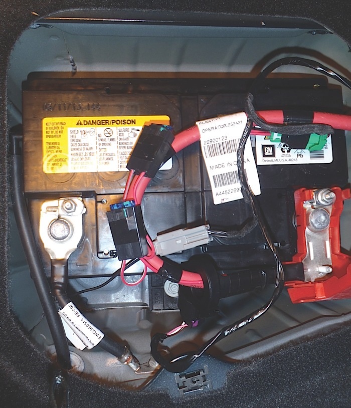
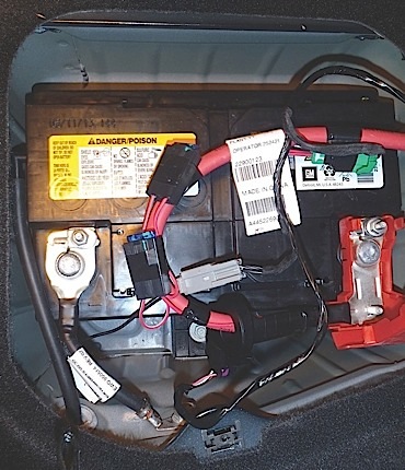
The battery current sensor is a serviceable component that is connected to the battery cables. The battery current sensor is a three-wire hall effect current sensor. The battery current sensor monitors the battery current. It directly inputs to the BCM. It creates a 5V pulse width modulation (PWM) signal of 128 Hz with a duty cycle of 0-100%. Normal duty cycle is between 5 to 95%. Between 0-5% and 95-100% are for diagnostic purposes.
Operation of Charging Systems
The purpose of charging systems is to maintain the battery charge and vehicle loads. There are 6 modes of operation and they include:
• Battery Sulfation Mode
The BCM will enter this mode when the interpreted charging systems voltage is less than 13.2V for 30 minutes. This can happen during extended idle times and can cause sulfation of the plates in the battery. When this condition exists, the BCM will enter Normal Mode for 5 minutes.
• Normal Mode
The BCM will enter Normal Mode whenever one of the following conditions are met: The wipers are on for more than 3 seconds; GMLAN Climate Control Voltage Boost Mode is requested by the HVAC control head; the estimated battery temperature is less than 32°F; speed is faster than 90 mph; current sensor faults are set; and system voltage was determined to be below 12.56V.
• Fuel Economy Mode
The BCM will enter Fuel Economy Mode when the ambient air temperature is at least 32°F but less than or equal to 176°F, the calculated battery current is greater than -8 amps but less than 5 amps and the battery state-of-charge is greater than or equal to 85%. The system voltage will be between 12.6-13.2V.
• Headlamp Mode
The BCM enters Headlamp Mode whenever the high or low beam headlamps are on. Voltage will be regulated between 13.9-14.5 volts.
• Voltage Reduction Mode
The BCM will enter Voltage Reduction Mode when the calculated battery temperature is above 32°F and the calculated battery current is greater than -7 amps but less than 1 amp. Its targeted set-point voltage is 12.9-13.2V.
Charge Indicator Operation
The instrument panel cluster (IPC) illuminates the charge indicator and displays a warning message in the driver information center (DIC) when the one or more of the following occurs:
• The ECM detects system voltage less than 11V or greater than 16V.
• The IPC receives a GMLAN message from the BCM indicating there is a system voltage range concern.
• The IPC performs the displays test at the start of each ignition cycle. The indicator illuminates for approximately 3 seconds.
• The ignition is ON, with the engine OFF.
Using just a meter to diagnose the charging systems rules of 12.7-14.1V could lead you to replace components that are still functioning within specification. The key to servicing these systems is to have access to a scan tool that can monitor the different modes of charging systems.