How it Works
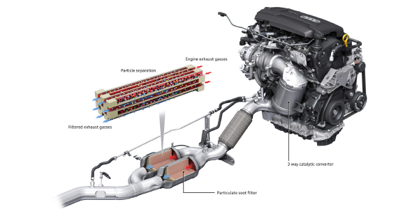
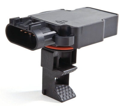
The mass air flow sensor (MAF) has become a standard part on most engine applications and is mounted in the intake air stream just past the air filter. It measures the amount of air (volume) in the intake flow by way of a thin wire mounted in the air stream. This wire is heated by the MAF with a pre-calculated voltage/current value. The heat generated by the hot wire is reduced as the intake air flows around it. The more air, the greater the heat loss.
Therefore, the electric current supplied to the hot wire is changed by the temperature of the hot wire as air flow increases. The ECM detects this air flow change through the current and voltage changes.
Faulty MAF Symptoms
You’d think a service light would be the first indicator of a problem, but there are times a problem develops with the MAF and no service light comes on.
Poor idle, loss of performance, sluggish performance and even stalling are all associated with a failing MAF sensor. Another indicator is an increase (and sometimes decrease) in short fuel trim (SFT) percentages.
Faulty MAF Causes
Contamination of the MAF hot wire is the main cause of failure. Air itself, even after it has gone through a perfectly good, clean air filter, is still not that clean. Over time, a build up of gunk will slow the reaction of the air, affecting the current flow for the meter. Cleaning the MAF helps in some cases, but replacement is still the best option.
Other causes of failure:
• Faulty electrical connections
• Sensor damaged from a collision
• Faulty wiring
• Faulty PCM
All of these can be determined when diagnosing the problem.
Scanner Diagnostics
A scanner with PID capabilities is a good method for diagnosing the problem. Rather than go straight to code reading, because there may not be any, I prefer to look at the SFT and the MAF PIDs.
Example vehicle: 2010 Nissan Versa, rough idle, no codes.
With the vehicle in park, the A/C off and engine warmed up (no other loads on the engine), the idle grams m/s should be 1.0 – 4.0 grams; at 2,500 rpms, the value should be 4.0 – 10.0 grams m/s. Knowing these values and watching the PID values should clue you in on the condition of the MAF.
This same PID check can be done on any vehicle if you have the specs, but what if you don’t?
MAF Diagnostics with a Multimeter
Basically, all MAF sensors have four wires.
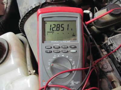
• Battery voltage 12-14V
• Ground lead
• 5V reference from PCM
• Signal return to PCM
If the MAF has more than four wires, the extras are for the intake air temperature sensor that has been incorporated into the MAF housing.
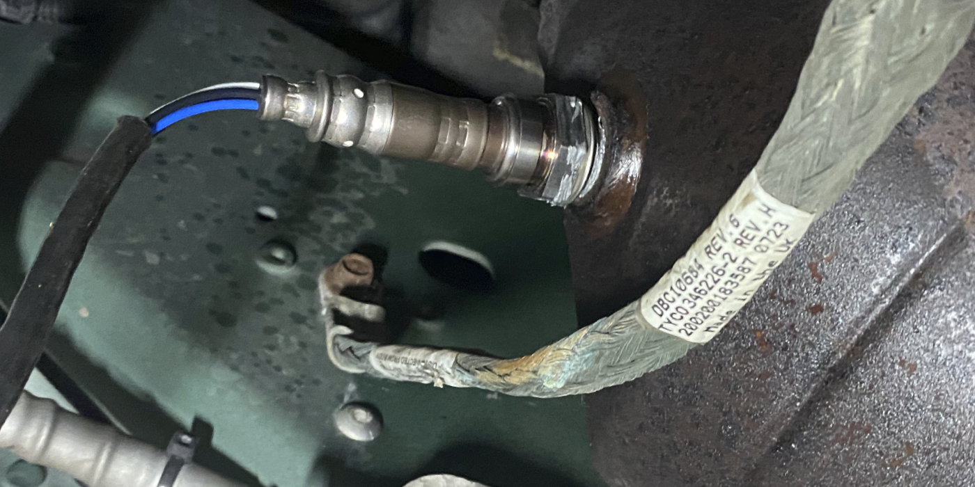
Three of those basic four wires can be checked without much
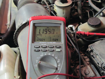
guesswork with a basic multimeter. The real key to testing with a multimeter is the signal return lead. This will be easy to spot because the return voltage will be less than 5V (or better be). If you test the other leads associated with the MAF and see another 5V reference and a return voltage, those will be for the intake air temperature sensor. We’ll sort those out in a minute.
MAF Snap Test
You’ll need one more thing to test this a bit further: Not just a
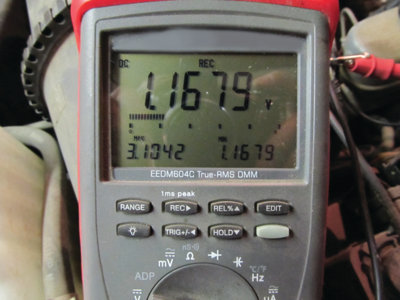
multimeter, but a multimeter with a “min-max” feature. This feature on the multimeter will allow you to record a voltage reading for a brief time. (You could use a scope for this too, but let’s keep this simple.)
Hook your min/max meter leads up — one to a good ground and the other to the return lead. Next, as quickly as you can, stomp the accelerator hard to the floor one time, and one time only. If it is
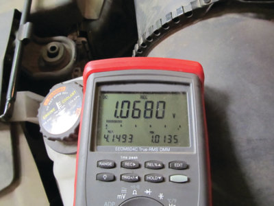
hooked up correctly and you’re on the right return lead, you should see an increase on the meter over or just above 4V. If not, assuming you’re on an MAF with more than 4 leads, try the other reference voltage lead. After all of that, if you still don’t see an increase over 4V on the meter, that MAF is certainly bad. (Note: There are a few older vehicles with a 3-wire MAF, but the reference return lead is still the same.)
There is one exception to this quick test, though: The Toyota 4-cylinder and some 6-cylinder engines. These will barely make it to 3.8V. Keep that in mind if you’re working with a Toyota product. Every other vehicle, import or domestic, will be at 4V. This quick test works without fail. Try it on a known good vehicle so you can see the results as they should look, and then you’ll be ready to tackle that problem car.