 By Matt Dixon and Ben Komnick, assistant professors,
SIUC (Southern Illinois University Carbondale) Automotive Technology
A good electrical course covers topics including AC and DC voltage, resistance, current, frequency and capacitance along with opportunity for application.
Recently, two vehicles provided us plenty of practice in all such areas.
Sometimes it literally takes all we know plus patience, suggestions from others and maybe a little luck to correctly diagnose invisible electrical challenges.
This story began innocently enough with an overheating complaint on the first vehicle.
The second had intermittent flickering headlights and instrument cluster gauge fluctuations, so it was an obvious challenge. We will attempt to convey what was learned in locating the target causes of these electrical challenges.
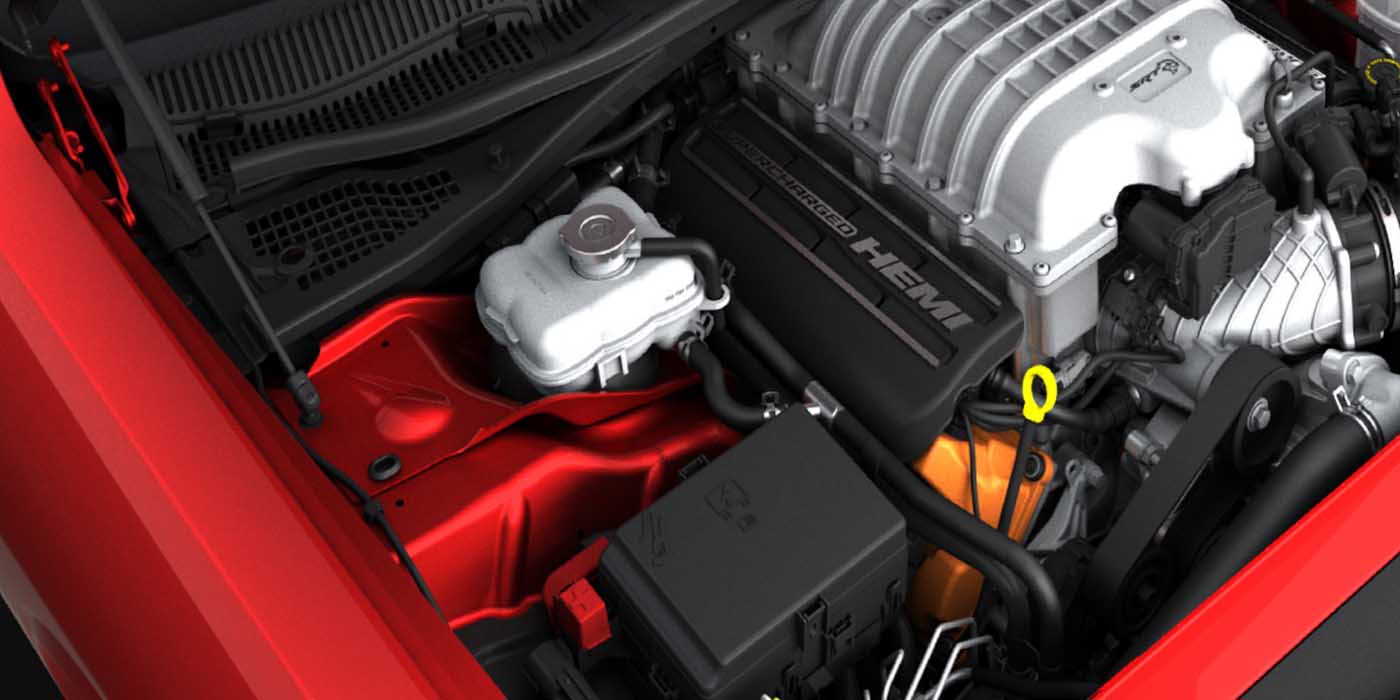
The first vehicle was a 2005 Chrysler 300C lab car. Lots of students and instructors worked on this car over the years, so you get the idea.
Keeping lab cars operational is at times like winning a troubleshooting contest. Students made darn sure the overheating complaint was verified.
It’s lucky no gaskets blew or heads warped.
In the process of boiling coolant in the overflow bottle, it was observed that the electric cooling fan did not operate unless the air conditioning was on.
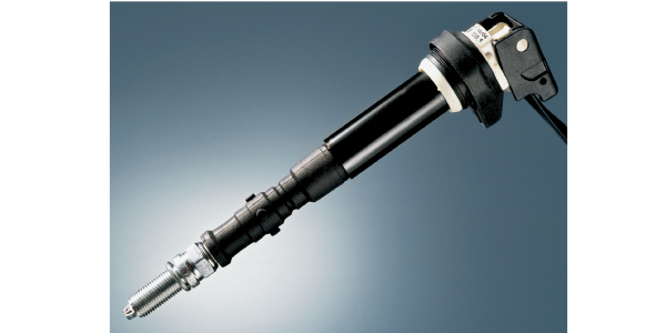
One student diagnosed it as a bad coolant temperature sensor (ECT). The diagnosis made sense and the part was ordered, but upon arrival, the connector end was wrong. The semester ended and sometime later the correct sensor arrived. 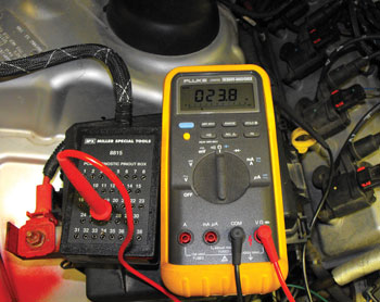
Ben, our body electrical instructor, installed it and with a quick operational check and lack of codes, it seemed like a done deal.
A few days later, Ben asked me to look at the car because it was running rich. I teach driveability so I was obligated. After jumping the abused battery, I quickly verified black smoke and a rough idle.
This vehicle had a history of oxygen sensor bugs so I installed a scan tool to confirm my suspicion.
Surprise, no codes, the upstream sensors seamlessly switched and the car began to smooth out.
I did notice fuel trims at minus 30% on both banks. Because of its replacement, the ECT sensor became the focus of my attention.
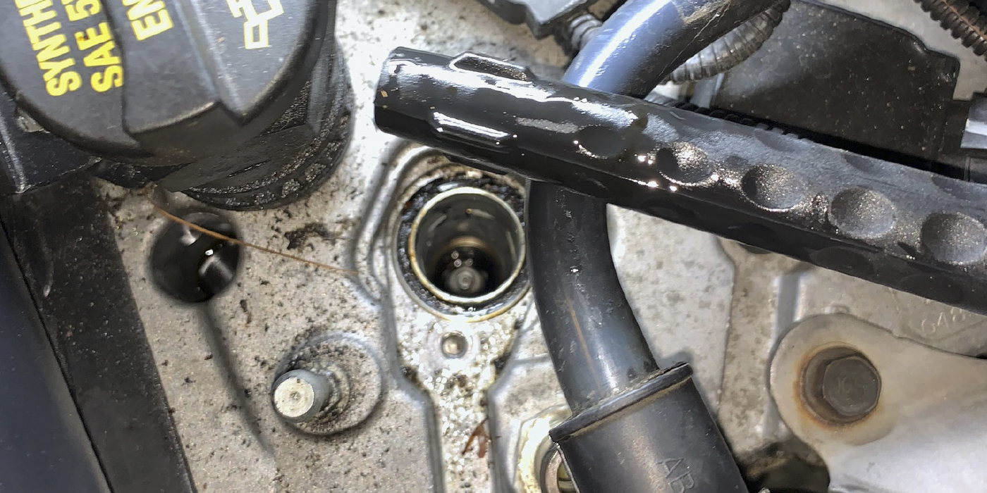
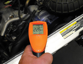
While watching temperature values to confirm operation, impatience led me to hold the engine at 3,500 rpm. Warm up never seemingly occurred. The return hose was hot, but ECT read only about 170°.
 I pointed an infrared temperature gun at the water outlet and it read 226° (see Figure 1).
As I quickly moved to switch off the ignition, I remember being mad, thinking the new ECT sensor was defective.
I decided to double-check the wiring before completely condemning the sensor. With the sensor disconnected, the wires measured 5 volts and ground.
Wiring was checking out, it must be that sensor! Comparing ECT on the scanner to the temperature gun, I observed a 40-50° discrepancy.
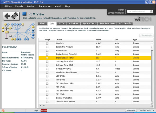
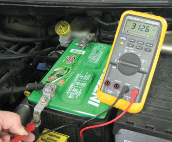
The coolant in reality approached 230° but the PCM reading was 180°. This explained why the fan was not activated. I also noticed barometric pressure (BARO) looked high for our area; it was over 32 inches of mercury when we are normally in the 29.2-30.0 range (see Figure 2).
 Two inches of mercury does not sound like much, but is nearly the equivalent of 2,000 feet of altitude. The manifold absolute pressure (MAP) reading was also high.
Other values appeared in range, but knowing MAP and ECT sensors share a sensor ground, planted a seed of suspicion.
I back-probed the ECT circuits to directly monitor voltage. The signal voltage matched the scan tool value, slowly dropping as the sensor got hotter.
The sensor ground circuit had over a tenth of a volt on it, almost enough to make me wonder.
Sensor ground is run through the PCM and electronically filtered to provide more accurate signal values.
We have a Chrysler 8815 pin out box, so I installed it on the corresponding PCM connector.
The circuits between the sensor and PCM each had under an ohm and just to be sure, we load-tested them with a jumper wire and a test light.
Ben wanted to measure resistance between sensor ground through the PCM to chassis ground. I disconnected the battery and we measured 20 ohms (see Figure 3).0
 Then, I almost made a wrong turn.
I was thinking 20 ohms sounds high, but the coolant sensor has a couple thousand ohms even at full operating temperature, not to mention the PCM uses a fixed resistor of 2,200 ohms.
So, I was almost ready to dismiss it, thinking 20 ohms compared to several thousand is trivial when I remembered the BARO and MAP values being off. The neurons in my brain started to fire.
After all, there was some voltage on the sensor ground.
This vehicle utilizes a speed density fuel injection system and given the high BARO and MAP values, along with a coolant sensor reading cooler than reality, an explanation of initial rich engine operation and high negative fuel trims was unveiled.
I decided to install an auxiliary ground jumper between sensor ground and the chassis to confirm my theory.
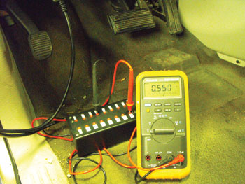
The vehicle started, and behold like magic, ECT, BARO and MAP values were back to normal (see Figure 4). After engine start, the fuel trims moved within 10% of zero. I removed the jumper and the readings returned to erroneous values.
 The fuel trims clocked quickly to minus 30. I had proven the fault was the PCM itself.
This vehicle challenge reminded me that voltage drops are very dependent on current flow. Since sensor circuits flow very little current, even a tenth or two of a volt can be significant.
The ground issue pushed sensor voltage up just enough to skew values, especially considering the single curve coolant sensor.
On this vehicle, the related symptom was the suspicious BARO and MAP values.
Now on to the paramount challenge, a 2005 Dodge Caravan with intermittent flickering exterior lights, instrument cluster gauges sporadically fluctuating and a radio that sometimes turns itself off.
This vehicle was purchased used by the customer and a repair shop had already replaced the battery and alternator in a repair attempt.
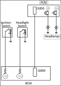
No aftermarket equipment was found nor any pertaining service bulletins. Each of the complaints was duplicated. This vehicle utilizes both a resistive multiplexed (MUX) ignition switch and headlight switch.
 The body control module (BCM) monitors switch voltage data and sends a request over the J1850 bus network to the front control module (FCM).
The headlights are controlled by the FCM, which pulses the power side of the circuit (see Figure 5). When automotive instructors theorize about cause versus symptom, things can get real interesting.
After over-analyzing the vehicle and hoping to tie together related symptoms, it was time for testing.
A scope and scan tool were used to verify stable headlight and ignition switch input voltages along with a properly operating bus network.
Only the complaint could not be duplicated in the shop. We noticed other oddities like the dome light not working. It’s controlled by the BCM and I was looking for a solid reason to condemn it.
 An investigation revealed the terminal end for the light had been removed from the BCM connector and covered with electrical tape. This is not the type of terminal that just anybody can remove without destroying. Someone had been here before and I wondered what kind of demented things they may have done to the van.
As it turns out, this was literally just a dead end.
Our testing was getting us nowhere fast.
Then Ben made an interesting find. He measured up to 700 mV of AC voltage at the data link connector (see Figure 6).
At first I thought he was testing for a faulty alternator, but the voltage was intermittent and was always 55 Hertz when present. This frequency was traced to the cooling fans that are controlled by a solid-state electronic relay.
The PCM pulses a command signal to the relay and it in turn pulses current to the fan motors to provide variable speeds. We considered the fan relay ground, so this and several other grounds were cleaned and tightened. This brought AC voltage down to 280 mV, but did not eliminate it.
The complaint could no longer be duplicated and the customer needed the van back. We crossed our fingers, but were soon informed that the van was displaying all of its terrifying symptoms.
 Talking with the customer we concluded the symptoms did not seem entirely heat related.
I opened an iATN help request and many online forums were searched. There were somewhat similar issues, but nothing that exactly matched. Several suggestions were made to clean grounds but no silver bullet.
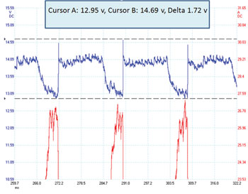
I contacted a friend at Chrysler. Again, certain grounds were mentioned, but also a prompt to think about the battery’s role as a capacitor. The AC voltage measured by a multimeter does not necessarily mean a sine wave form switching between negative and positive. In our case, a rhythmic disturbance was causing vehicle voltage to swing higher and lower of average charging system voltage (see Figure 7).
The meter set on AC voltage measures peak-to-peak fluctuations and displays an RMS (root mean squared) value. The vehicle battery acting as a capacitor should act to dampen such swings.
Soon the vehicle returned to our lab and we had grandiose plans of swapping components including FCMs, alternators, fan controllers and BCMs one at a time from a like vehicle. Before getting too carried away, we decided to double-check some basics. It was a good move.
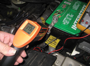
 Voltage drop tests were performed on battery terminals during cranking. A half-volt drop was measured between the negative post and wire strands within the terminal crimp. During testing, a stroke of luck, my hand bumped the terminal crimp and it was hot. The vehicle was then started and all accessories switched on.
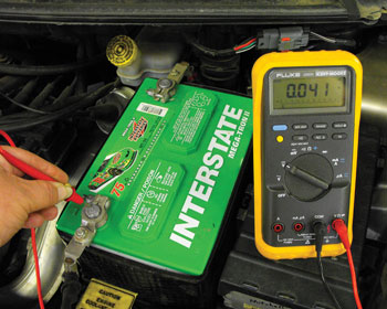
A temperature gun measured 173° F on the crimp (see Figure 8). Visually the crimp and terminals looked showroom new. Despite the heat, DC voltage drop at this point was less than a tenth of a volt (see Figure 9). AC voltage was still high at the data link connector and diminished approaching the battery.
Measurement across the battery posts yielded 100-200 mV. An AC voltage drop between the negative post and wire strands within the terminal crimp revealed over 300 mV (see Figure 10).
This vehicle’s negative cable is serviced with the entire engine harness so we wanted to be extra sure of our diagnosis. We connected an auxiliary 2-gauge cable from the battery terminal to an engine ground stud. AC voltage decreased somewhat as well as crimp temperature.
Then, an auxiliary cable was routed from the negative terminal to body ground G102. This multiple eyelet stud grounds the fans and relay. Once installed, the crimp was no longer hot and most AC voltage was gone.
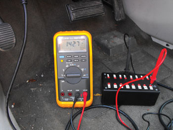
We compared readings with two other properly functioning Caravans and found a consistent 130-140 mV AC at the data link connector (see Figure 11). The complaint could no longer be duplicated; the crimp was proven as root cause. Resistance in the crimp caused only a relatively minor DC voltage drop, but appears to have contributed greater than expected interference in the battery’s capacitor role.
After solving these challenges, it was time to reflect on lessons learned. First was a reminder to utilize readily available tools including the AC voltage and frequency functions of a digital multimeter. I was reminded that voltage drop measurements are very dependent on the amount of current flowing. A generic rule of thumb specification of 0.1 or 0.2 volt does not always work.
The vehicle battery is not only a source of current, but also functions as a capacitor. Also, noting related symptoms can sometimes be very helpful. Despite industry trends of complexity, using multiple modules and networks to control functions such as headlights, this problem was caused by a simple battery terminal crimp.
Then again, as the first vehicle demonstrated, sometimes a module can be the problem. There are no silver bullets in diagnosing the invisible nature of electrical faults. It takes knowledge, testing, patience, suggestions from others and sometimes luck to illuminate the actual cause.