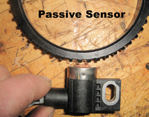
There are two main types of magnetic wheel speed sensors — passive and active. Both use a tone ring to reference against and each look very similar to one another. As the raised portions of the tone ring pass by the tip of the sensor, the sensor creates a signal. The passive type of sensor is a simple AC signal generator. As the teeth pass the sensor, it produces a sine wave. As the wheel speeds up, the frequency of the sine increases as well. The ABS module reads the frequency to determine the speed of the wheel. The downfall with this design is that the frequency is not the only thing to change with rotational speed. The amplitude also changes.
The faster the wheel turns, the greater the peak voltages are. The high end of that aspect is not a problem. The problem lays in the low end. When the wheel is turning at very low speeds, such as under 3 mph, the sensor becomes unreliable because it is barely producing a readable signal to the ABS module, especially when wiring resistance and RF noise are factored in. You may notice that a scan tool will show the wheel speeds starting at 3 mph for these types of sensors. Some scan tools might report 3 mph when sitting still, and others might report 0 mph until a vehicle speed of 3 mph is achieved and suddenly the PID will jump from 0 to 3 mph. That is normal for a vehicle with passive wheel speed sensors. These sensors can be tested for coil circuit integrity with an ohm meter. More preferred methods of testing are AC volt meter for voltage output and oscilloscope.
To get reliable readings at very slow speeds, the active wheel speed sensor is employed. An active wheel sensor has a tiny processor chip in it that reads the tone ring with the same signal generator method as the passive speed sensor, but does not use that conventional signal to share with the ABS module.
Instead, the ABS module sends the sensor a 9 volt power supply and the active sensor produces a square sine, also referred to as a modified sine wave. It is a digital high/low toggle rather than an analog voltage ramp-up like with passive sensors. Since the chip can read the minute voltage generated at the coil end of the sensor and convert that to a signal to the module, it can read speeds below 3 mph reliably.
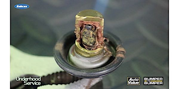
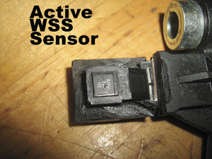
The amplitude of this signal to the ABS module does not change with speed, only the frequency does. An ohmmeter can not be used to test the coil side of the sensor. If you use an ohmmeter on it, you will get a measurement because the ohmmeter will find a path down one wire, through the chip, and back up the other wire. But that will not be an indicator of the coil windings at the sensor tip. The preferred methods are with an amp meter that can measure in the 7mA to 14mA range and an oscilloscope. A DC voltmeter can be used to test the ABS module’s ability to send voltage to the wheel speed sensor. In the picture here, labeled active wss, the housing of the sensor has been ground away so that you can see the tiny little processor chip inside.
DIAGNOSIS
The first signs of trouble may be the ABS system kicking it when braking at low speed, and/or the ABS warning light coming on. Until you hook up a scan tool and pull the codes, though, there’s no telling why the light is on. The fault may be a bad wheel speed sensor or it might be something else, so don’t jump to conclusions — especially if there are no codes to guide you.
Reading ABS codes requires an ABS code reader, scan tool or scanner software that can access the ABS system. An inexpensive OBD II code reader or an entry-level scan tool designed for a do-it-yourselfer won’t work here. You need a professional tool designed for ABS diagnostics, or a digital storage oscilloscope to look at the wheel speed sensor waveforms.
If the ABS light is on and you find a code for a wheel speed sensor, check the sensor wires for breaks or a loose/corroded connector. Broken wires are probably the leading cause of wheel speed sensor related failures. One some vehicles, the wires tend to be brittle and break as a result of fatigue from road vibration and/or steering maneuvers. Replacing the WSS wiring harness is usually the recommended fix for these situations. You could try to patch the broken wire, but crimp connectors are vulnerable to road splash and corrosion, and solder is usually too rigid and will crack again. Better to replace the wiring harness than to risk a comeback.
If there are no codes, but the vehicle owner complains about the ABS system engaging when braking (noise, vibrations and pedal pulsations), the problem is likely a bad wheel speed sensor. But which one? That’s where a scope can really help you identify which sensor is acting up. Connect the scope to the sensor leads and spin the tire by hand. If you get a good clean signal, move on to the next WSS sensor and so on until you find the one that is generating a bad signal.
If the scope pattern produced by the sensor is flattened (diminished amplitude) or is erratic, it usually indicates a weak signal caused by an excessively wide air gap between the tip of the sensor and its ring, or a buildup of metallic debris on the end of the sensor. A weak signal can also be caused by internal resistance in the sensor or its wiring circuit, or loose or corroded wiring connectors. You can also measure the wheel speed sensor’s output with a DVOM. The most accurate way to do this is with a breakout box connected to the wiring harness at the ABS module. You can also connect the DVOM test leads directly to the wheel speed sensor itself, but testing the sensor this way won’t tell you if the signal is getting through to the control module. Spin the wheel by hand and note the sensor’s voltage reading.
A good wheel speed sensor will typically produce an alternating current (AC) voltage reading of 50 to 700 MV when the wheel is turning one revolution per second.
If the voltage reading is low or nonexistent, check the sensor’s resistance (with the key off). This should also be done at the breakout box. Checking resistance of the wheel speed sensor circuit where it plugs into the module will tell you if the sensor’s wiring harness is OK. If you don’t get the specified value (typically 900 to 1,400 ohms), go to the wheel and unplug the sensor from its wiring harness, then measure the sensor’s resistance by attaching the DVOM test probes directly to the sensor leads.
A resistance reading that is now within range tells you the problem is in the wiring, not the sensor. If the sensor itself out of range, high or low, the sensor is defective and the sensor or hub assembly (if the sensor is not removable) needs to be replaced.