You will see only one fuel line going to the fuel rail on most late-model vehicles. Instead of using an engine vacuum routed to a pressure regulator under the hood, returnless systems use engine data and vary the speed of the electric pump to meet fuel pressure and volume requirements without having to bleed off and return it to the tank when the engine does not need it.
Modern pumps do not vary the voltage to the pump; rather, they pulse the power to the pump. Instead of pumping at 100% for 100% of the time at 12 volts, the pulses are changed so the pump supplies enough pressure and volume for the different conditions. This strategy means less current going to the pump, which means less heat and a longer life for the pump.
Managing the speed of the pump electronically instead of using a mechanical pressure regulator on the engine simplifies the fuel system by getting rid of the return line and vacuum pressure regulator under the hood. Other benefits include lower fuel temperatures in the tank and less of a chance of vapor lock.
How does a pulse-width modulated pump work?
The driver for the fuel pump switches 12 volts off and on to control the speed of the fuel pump. The longer the time the voltage is turned on, the faster the pump will turn and more fuel will be pumped. This is done with a solid-state transistor and there are no moving parts inside a module. When the circuit driver fails, the pump will stop working.
How is it measured?
The ratio of “on to off time” is called the duty cycle. The duty cycle is the fraction of one period in which the voltage is on compared to the off time. A constant 12 volts is a 100% duty cycle. If you had a pump with a 1-second cycle and the driver switches the voltage on for 0.3-seconds, it would be a 30% duty cycle.
Don’t confuse duty cycle with Hertz (HZ). Hertz is measured on a sinusoidal wave of alternating current, where pulse-width voltage waves are square and represent a positive voltage switching.
How does the fuel pump look on a meter?
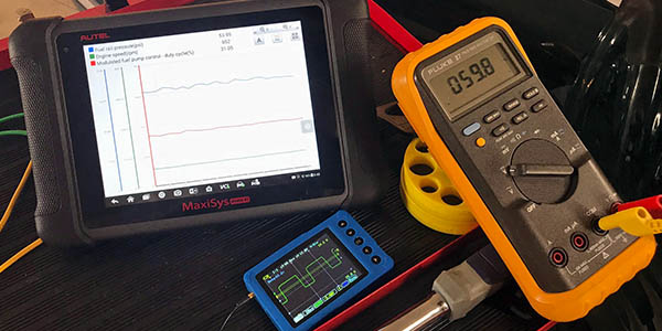
A full-feature voltmeter is critical to diagnosing modern fuel pumps. The meter should be able to measure the duty cycle and have a min/max function.
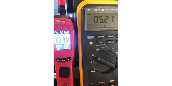
If you use a meter and back probe into a pulse-width modulated fuel pump circuit, it might display only 3 to 7 volts in DC volt mode. Also, the last two digits on the display might be jumping around. If you switch your meter to AC voltage, the voltage reading will be close to the DC voltage.
To the untrained technician, they might assume the power being delivered is not sufficient to run the pump due to the 3- to 7-voltage reading. The truth is the 3- to 7-volts is just an average of the high and low peaks of the pulse powering the fuel pump. This is what the Root-Means-Square (RMS) feature is designed to do when reading some DC and AC voltages and displaying an average.
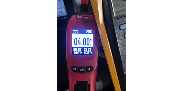
If the meter has a min/max function, you can see a peak voltage that should be close to the battery voltage and low voltage would be between 0 and 0.5 volts. This is a sign that the voltage and driver powering the fuel pump are healthy. If you saw a max voltage lower than 12 volts, you might want to check for high resistance in the circuit.
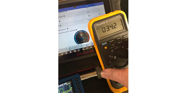
If the meter has a duty-cycle function, it is possible to measure the on and off times and determine the ratio and display the duty cycle as a percentage. The duty cycle percentage can be compared to the scan tools data and the PIDs for commanded fuel pump speed or duty cycle.
Scopes
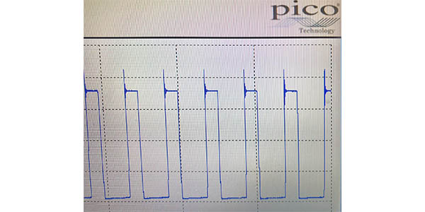
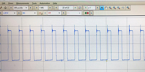
With a scope, it is possible to graph the switching of the duty cycle. The scope can be used to spot glitches and the dropping out of the pulse-width modulated signal. You should be able to see if the driver is switching between 0 and 12 volts. The scope can also monitor the current consumption of the fuel pump with a current clamp.
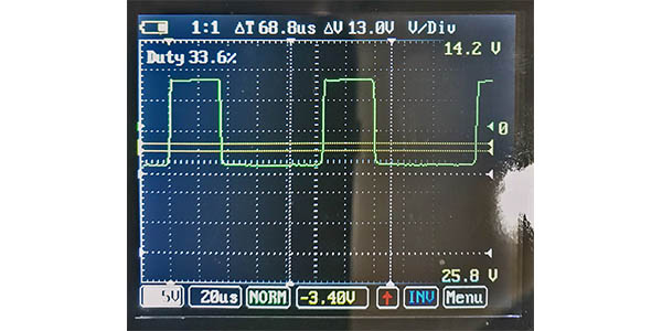
The waveform should have a clear square wave. If you have a fast scope with a high sample rate, you can see small ripples when the transistor turns the power on or off. As fuel demands increase, the upper part of the wave will increase in length.
Scan Tools
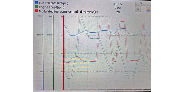
A scan tool is essential to solving pulse-width modulated fuel pump problems. With a scan tool, you can observe the commanded duty cycle or speed for the fuel pump.
If you can graph the PIDs for the commanded speed/duty cycle, fuel pressure and engine speed, you can get an indication of the health of the fuel pump. If you hit the throttle, the speed/duty cycle of the pump will jump upward, while the pressure remains within an 8-psi range. A healthy fuel pump’s pressure reading will not fall below the specified minimum range. If you see the fuel pressure dropping or taking an extended period to recover after a load is put on the engine, the pump is worn out.
Scan tools can also capture codes for the fuel system that can hold freeze-frame information that can show fuel pressure readings.