CIRCUIT DESCRIPTION
The commanded throttle position is compared to the actual throttle position based on accelerator pedal position and possibly other limiting factors. Both values should be within a calibrated range of each other. The PCM continuously monitors the commanded and actual throttle positions. DTC P1512 sets if the values are greater than the calibrated range.
This article will document the infamous code P1512 – “Throttle Position Not Learned.”
P1512 is a code that involves electronic throttle control (ETC), or throttle actuator control (TAC), and in many situations, a technician may be tempted to replace the throttle body assembly right away. This article will attempt to provide a better plan of attack.
I have found through my research that all of the car manufacturers appear to have similar logic on how these systems may work, but keep in mind you must study each one of them in detail for proper diagnosis and repair.
Our diagnostic journey will begin with a General Motors product.
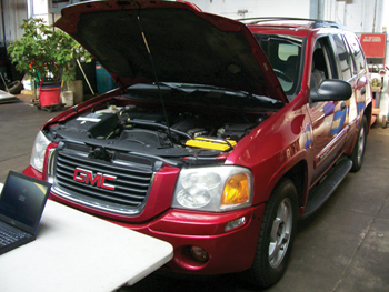
Our subject vehicle for this Pulling Codes case is a 2002 GMC Envoy. This vehicle has entered the shop with the “reduced engine power” lamp on. The engine was running very poorly and the vehicle could not be driven. After the ignition key was cycled off and then on again, and the vehicle was then restarted, it would run as if there was no issue with it whatsoever. The technician witnessed this event and replaced the throttle body assembly.
The vehicle ran fine for a few days and returned to the repair facility with the same complaint later in the week. So now let’s review the trouble code chart as well as the enabling conditions for this code.
The code is set when the commanded throttle position sensor (TPS) values do not agree with the actual TPS values. The throttle valve of the throttle body is spring loaded to a slightly open position. The throttle valve should be open approximately 20%. This is referred to as the rest position. The throttle valve should not be completely closed nor should it be open more than the specified amount (20%). The throttle valve should move open and to the closed position without binding under the normal spring pressure. The throttle valve should not be free to move open or closed without spring pressure. If binding or free movement is noted, the throttle body should be replaced. 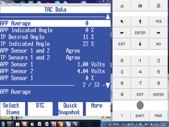
The scan tool has the ability to operate the throttle valve throughout its entire range to verify if the system is operating properly.
A review of the TPS values in the screenshot in Figure 1 shows a TP desired angle of 11%, while the actual angle is at 22%. This exceeds the 20% that was mentioned earlier.
The ignition key is then cycled off and the values were displayed at 9% for both PIDs, see Figure 2. 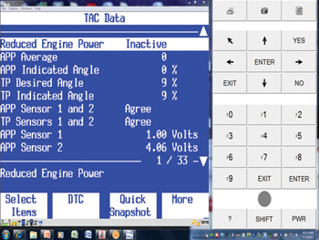 The ignition key is then cycled on again and the value changes to 9% for desired and 22% for actual, see Figure 3. The 22% would explain the reduced engine power lamp being illuminated. The following screenshots show the data as we witnessed it.
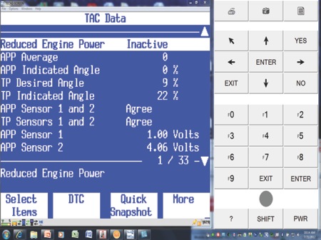
It is also interesting to note that as the throttle was moved back and forth by foot, the values for the TP sensors would go within range and the vehicle would run fine. The technician working on the vehicle thought that it must be a bad throttle body assembly again and wanted to order another one from the dealer. I stopped him and asked him the first question I like to ask when electrical issues similar to this occur, “Did we check all power, reference voltages and grounds for this circuitry to work properly?”
We began this process by reviewing the schematics that show the relationship between the ETC and the PCM, see Figure 4. 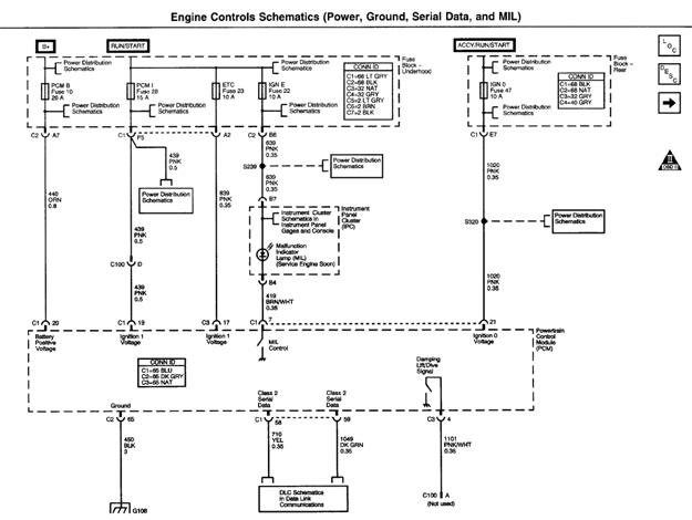 It always appears that there is more to the story, and a little homework revealed that an additional schematic was in need of review, see Figure 5. The schematic for power and grounds showed that there is an ETC fuse that provides power directly to the PCM.
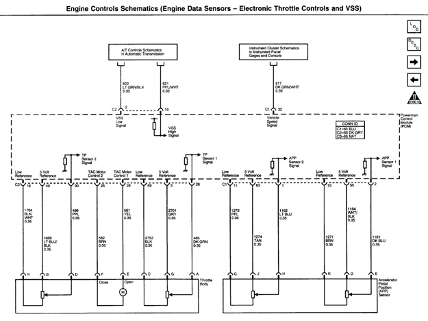
We checked the ETC fuse (Figure 6) for voltage and we found that there was no voltage on this circuit. The circuit runs from the fuse box directly to the PCM. It appears it is a critical circuit that is needed in order for the ETC to work properly. The technician repaired the circuit and checked the system for integrity. 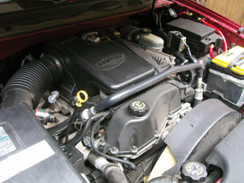
A diagnostic system check was performed on the system and the following information is revealed in Figure 7. We now have an all-system pass. 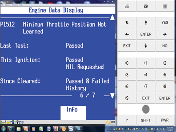
It is very interesting to note the possible reasons why this ETC fuse is so important to the PCM and its interpretation of throttle position, the PCM operates the throttle control motor to verify the integrity of the system prior to start-up. If this fuse is blown or we have an open circuit, the position of the throttle cannot be accurately determined per the PCM. A code indicating that the throttle position has not been learned is set.
This Pulling Codes case is solved.
 Note: There is a great video from AVI on this subject and offers an engineering perspective into the operation of the GM ETC system.
Go to auto-video.com and search for “GM Electronic Throttle Control” with AVI instructor Dave Hobbs (LBT-141).
In this 90-minute course, Hobbs gives you an overview of the system, including theory of operation, design variations and ETC default codes for GM vehicles. Case studies and on-vehicle tests are also included in this program.
Hobbs explains how the system has changed and provides a detailed explanation of the five default modes and tells you how they work, why we need them and the strategies behind them. He also reveals cleaning tips for the throttle body that you need to know. — CB