U Code, Not Me Code
This has truly become the “theme song” of many modern-day controllers. This Pulling Codes article will center on issues involving the powertrain control module (PCM) talking to your scan tool. In many states, this is the controller our scan tool needs to talk to in order to determine if the correct number of monitors has run and passed.
It’s interesting to note that there appears to be two modes of failure in terms of communication.
The first mode is where the module will not communicate and has a U code stored in memory, it does not communicate on an enhanced or generic level.
The second mode of operation is where the module may not have a U code stored in memory, but communicates on an enhanced level, but not on a generic level. This mode has been the most challenging for many emissions testing states.
It is also interesting to note that the U code we have for our subject vehicle — a 2006 Pontiac G6 — has an ID number within the body of the code to identify which module is not communicating. The U code will always be stored in a module that does communicate with your scan tool. This is not an indication that there is a problem with the module that is talking; the module that is talking is pointing to the guilty party that will not talk.
A good example of this would be a BCM on a 2004 Chevy Tahoe, showing a code U1016 stored in memory; this indicates that it has lost communication with the PCM. The 016 within the body of the code identifies the PCM as the guilty party. A list of these ID codes appears in the service information for this year, make and model.
The question that now arises is “How do I test for a no communication issue?”
The first items you’ll need to verify are power and ground circuits for the data link connector (DLC). You first need to disable the vehicle so that it cranks, but doesn’t start. You’ll then perform a voltage drop check on the system ground. (The use of a DLC breakout box is preferred for testing, see Figure 1.) 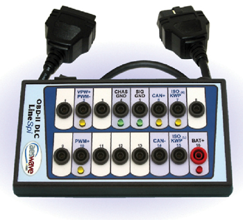
Next, you’ll attach one meter lead to Pin #4 of the DLC and the other lead to battery negative with the engine cranking. You’ll perform the same test on Pin #5 of the DLC to battery negative as well. This is a good dynamic test that should show a voltage drop of 0.2 volts or less.
The next test on the DLC will be to check Pin #16 for battery voltage. You must always refer to service information to verify that you are testing the proper pins. See Figure 2. 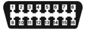
The next step is to check communication circuits; there are terminating resistors that are used to reduce electrical noise on these communication circuits. A review of the schematics that refer to vehicle communication for the vehicle you’re working on is a valuable asset to properly diagnosing a communication issue. It’s strongly recommended that a DLC breakout box be used for testing.
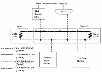
The first test procedure here is to check between Pins #6 and #14 of the DLC with an ohmmeter. This resistance check should yield a resistance value of approximately 60 ohms (Figure 3). A system diagram is shown in Figure 4 as an example for review.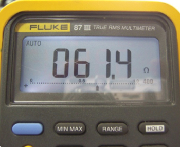
The next test is to check voltage information on DLC pins #6 and #14. Pin #6 is normally denoted as CAN H and Pin #14 is normally denoted as CAN L. The voltage information can be checked with a voltmeter or lab scope. If a voltmeter is used, it’s important to note that a peak min-max function should be used with a time testing window of 1 ms or less. The voltmeter cannot tell you the quality of the signal being produced. A lab scope gives a visual picture of the electrical quality of the signal that is present. (A sample pattern is shown for reference, see Figure 5).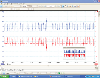
CAN H will have a voltage range of 2.5 to 3.5 volts, whereas CAN L will have a range of 2.5 to 1.5 volts. The wiring on the vehicle must be checked for shorts to ground, voltage or opens. If wires are next to each other, it’s also possible for wires to be shorted to each other. In many cases, frayed wiring has contributed to lack of communication on many of the vehicles tested.
It’s also important to be able to attempt communication with the vehicle on the generic as well as the enhanced side. It’s possible for it to communicate one way and not the other. When a vehicle is at the test facility, the communication attempt is made on the generic side.
In closing, the breakout box provides a way to view the communication activity under dynamic conditions. Always check all feeds, all grounds and serial data to a module before any replacement is considered.
In Review
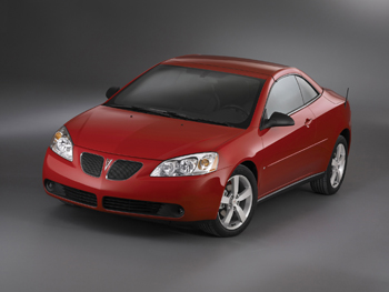
Let’s now review our case study for this month. We have a 2006 Pontiac G6, in which the Tech 2 will communicate with the PCM, but a generic scan tool will not. The vehicle has been to the state test facility and doesn’t communicate with the equipment there either.
A schematic outlining the protocol architecture for the vehicle was obtained. It uses a GMLAN, which is CAN data. A schematic was reviewed first to see the architecture of the protocol. An ohm test was performed between pins #6 and #14 of the DLC, an ohm reading 0.505 Mohms was noted on the DVOM.
The terminating resistors for this vehicle are located in the PCM and BCM of this vehicle. The BCM was disconnected first and the same ohm test was run on the vehicle, this second ohm test showed 120 ohms. The BCM was reconnected and the PCM was now disconnected, this third ohm test showed 120 ohms. The PCM was reconnected and a final ohm test was performed on the vehicle. The final reading was 60 ohms.
It was now clear to this observer that a poor connection existed between the two modules. This Pulling Codes case is now closed.