For this month’s Pulling Codes case, we will attempt to provide a plan of attack for communication issues on General Motors products with the Class 2 Protocol.
Our diagnostic journey begins with a 2004 Chevrolet Tahoe.  This vehicle was tested at the EPA test facility in our area and it was determined that there is no communication with the PCM.
Our subject vehicle is taken to a local repair facility to be evaluated. The first step there is to confirm the no communication issue. The technician uses a Tech 2 scan tool to access data and the scan tool is able to communicate with the Tahoe without a problem. So, he calls the EPA test facility to report that the vehicle does not have a communication problem. The state responds in a very pleasant manner and advises the tech that the vehicle must communicate with their equipment in order to pass the emissions test. 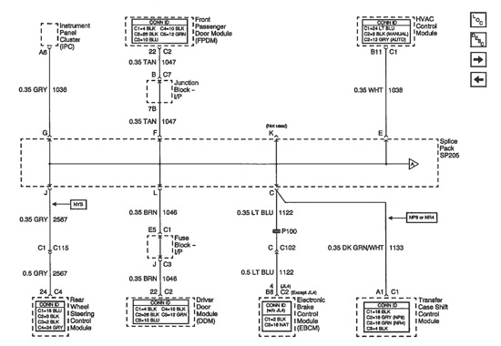 It’s interesting to note at this time that the state communicates on a generic level. The tech takes out his generic scan tool and finds that the vehicle does not communicate with it. The problem has been confirmed.
The first step in our diagnosis is to review schematics for the communication lines. Figure 1 denotes the circuitry.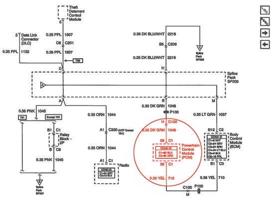
The PCM is denoted in Figure 2. Now we have a complete picture of what our testing will entail. A comb device will be removed out of the splice pack (Figure 3) to take all of the modules on the schematic offline momentarily. The modules will then be placed back online one by one.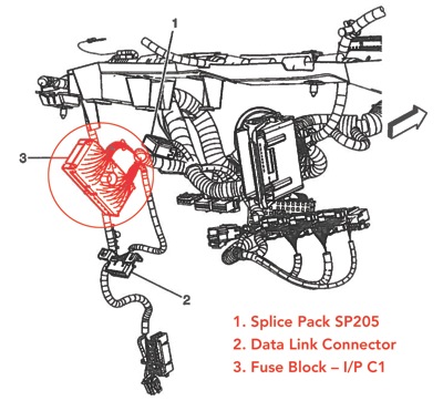
A lab scope is placed on the data line to view the quality of the signal. A jumper wire will be used to place each module back online one by one to view the serial data quality for each one. The serial data line is a 0 to 7 volt pulse, which is pulse width modulated. Figure 4 is an example of a known-good pattern for your review. 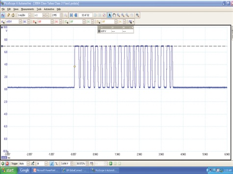
The jumper wire was used to bring each module back online one by one, a pattern showing
0-7 volts was seen by all of the modules except one. If your guess was the PCM, you are incorrect! An example of the bad pattern is shown in Figure 5 for your review and analysis.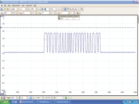
This pattern showed a range of 0 to 5.8 volts, this was below the threshold needed in order for proper communication to take place on this vehicle. The bad pattern occurred on the circuitry for the SDM or sensing and diagnostic module (airbag module). The airbag module circuitry was loading the circuit to this value, causing the PCM not to communicate with the generic scan tool. The pin for the airbag module was taken off the bus and generic communication was restored.
The vehicle then passed the emissions test, and the repair shop was advised to repair the airbag circuit.
This Pulling Codes case is now closed.
Note: If you’re interested in reviewing websites that provide examples of known-good waveform libraries on a variety vehicles and vehicle systems, you can contact me at [email protected] and I will provide you additional information.
Want more? Check out this AVI video:
F.R.E.D. Takes the Bus
Data-bussing and multiplexing can be complex and aggravating, but F.R.E.D. (Frustrating, Ridiculous, Electronic Devices) can help solve the mystery behind it. In this program from AVI (LBT 73), Dave Hobbs brings his 30+ years of experience to show you how the electronic modules communicate with each other and help you tackle this tough issue and save diagnostic time.
Dave uses hands-on demonstrations with the Snap-on MT2500, the Vetronix Tech 2, and the Mastertech to explain data bus layouts, voltages, wiring and baud rates. He tells you what to do when your scan tool says “no data” or its display flashes. Dave explains the difference between a “UART data bus” and a “class 2 data bus” and the difference between loop and star configurations.
Other highlights:
• How to “ping” a module to find out if it is active;
• Explains terms like “binary” and “hexadecimal”; and
• Case studies on no-start and no-communication issues.
Runtime: 75 minutes, Manual Included
Visit www.auto-video.com/fred-takes-p-18.html to order.