Although post-1996 OBD II powertrain control modules (PCMs) are generally very reliable, we’re beginning to see more failures because the average age of our national vehicle fleet has now increased to about 11.5 years. Technically speaking, the PCM should store a DTC indicating some type of internal malfunction. But, in the real world, if your scan tool indicates “no communication” and asks if the ignition switch has been turned on, you obviously have a communications problem. Your first step is to verify that you have entered the correct VIN and, if your scan tool requires a vehicle “personality” key to communicate with the PCM, verify that the key is correct for the application. Next, test the battery for a poor state of charge (SOC) and state of health (SOH) before beginning any PCM diagnosis. If defective, the battery should be replaced or substituted before continuing with the diagnosis.
In other cases of no communication, the scan tool should have automatically identified the VIN but, for whatever reason, it did not. With that in mind, I usually begin a no-communications diagnosis by testing the throttle position sensor or other easily accessible sensors for the presence of the 5-volt reference signal that should be originating from the PCM.
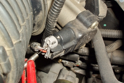
If the 5-volt reference is present, it’s likely that the PCM is at least partially operational. If not, it’s possible that a shorted sensor is pulling the 5-volt reference to ground, in which case the best procedure is to disconnect various sensors until the reference voltage comes back on line. See Photo 1.
I’ve also had some PCMs fail to communicate with the scan tool because they’ve been ruined by excessive charging voltage, water intrusion or other catastrophic occurrences. If this is the case, consult a PCM connector diagram to determine the configuration of the connector pins.
Most PCM connectors contain a battery voltage (B+) pin, a key-on voltage pin and two redundant battery ground (B-) pins. The B+ pin, which is fused, maintains the PCM’s keep-alive and diagnostic memories when the ignition is turned off. The key-on pin supplies voltage to the PCM and indicates when the ignition is turned on. In some applications, key-on voltage is supplied by a PCM relay.
If voltage isn’t available at the B+ pin, use a voltmeter to test both legs of the PCM or engine control module (ECM) fuse for battery voltage. If testing doesn’t indicate nearly full battery voltage, consult a wiring schematic for areas that might affect the PCM’s voltage supply. If key-on voltage is say, two volts less than battery voltage at the key-on pin, suspect a bad ignition switch.
At least 9.5 volts should be available at the B+ and key-on pins during cranking to ensure that the PCM is operating correctly. With the key on, test the redundant PCM grounds for a voltage drop of more than 500 millivolts (mV) between the pin and battery ground.
DLC Testing
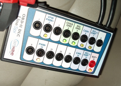
The data link connector (DLC) is numbered from left to right beginning at the upper left corner. Use a DVOM to check pin No. 16 on the DLC for battery voltage (B+). If B+ is present, test pin Nos. 4 and 5 with a 1.5-volt ohmmeter to ensure that they’re connected to chassis ground. I would not recommend using a 12-volt continuity tester for checking the DLC ground circuits because the remaining 13 pins are low-voltage communications bus circuits. See Photo 2.
A better method for testing DLC pin activity is to use one of the several DLC breakout boxes (BOBs) now selling in the $200-$300 range on the general market. While I’m only going to touch on the application-specific topic of bus communications, the DLC BOB will allow the technician to instantly evaluate B+ at pin No. 16 and the integrity of ground pin Nos. 4 and 5.
In addition, the technician can use a labscope or multimeter to monitor circuit activity on each communications bus pin. Remember that the remaining pins require a DLC connector diagram to complete an accurate bus communications diagnosis. See Photo 3.
Polling The Modules
Here again, we’re touching on communications bus diagnostics, but if the scan tool is communicating, it’s time to poll all modules for both communications and DTCs. In some cases, a “no communication” message for a particular module might indicate that the module is not present or not included in the scanner software. Remember that practically all late-model vehicles contain, at the minimum, an engine/powertrain, anti-lock brake, theft deterrent/vehicle security, safety restraint (air bag) and body control module. Higher-end vehicles have many more computers and modules, but here again, adequate training, database and OE-level scan tool capability are required to evaluate these more complex systems.
Bidirectional Controls
In some cases, one portion of a PCM might become non-operational due to a problem with the PCM’s processing capability. Consequently, all such controls and tests should be activated to ensure that the PCM is responding to bidirectional commands.
Bidirectional controls are also valuable for testing the individual accessory drivers contained within the PCM, such as the ignition coil and fuel injector drivers. The PCM, for example, might control starter engagement via a PCM-operated starter relay. If the starter relay doesn’t “click” when commanded, the PCM’s starter relay driver might not be pulling the relay control circuit to ground.
Intermittent Failures
In most cases, there is no definitive method for diagnosing an intermittently faulty or “schizophrenic” PCM. In my experience, most PCMs operate at about 110-120° F temperature at 70° F ambient air temperature. When testing a suspected intermittent PCM failure, I use a small hair dryer set on low heat to duplicate normal PCM operating temperatures.
But I’ve also had PCMs reside in unusually hot areas, such as the engine firewall or over the heater blower housing, so it’s possible that actual operating temperatures might approach 150° F. As the PCM is warming up, tap the PCM case with a screwdriver handle to simulate mild road and powertrain vibration. In many cases, this test will disclose temperature and vibration-sensitive circuit failures within the PCM itself.
A final issue is moisture or fretting corrosion on the PCM pins. Because pin corrosion is virtually invisible, I often use a small artist’s brush to apply a conductivity enhancer like Stabilant 22 to the PCM pins. In some cases, this is a permanent repair for a troublesome intermittent PCM malfunction.
Rationalization
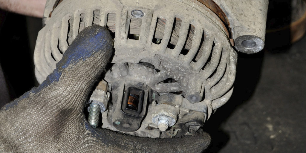
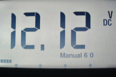
Once in a great while, a PCM simply won’t display a correct value for a particular parameter identification (PID). To illustrate, I had a PCM disable an alternator field circuit because the voltage PID falsely indicated 17.5 volts, which is a threshold over-charging condition. Most recently, I found another PCM that displayed 14.2 volts on the instrument cluster and on the scan tool display, which is well within a normal charging voltage range. But, despite the indicated voltage, the PCM wasn’t grounding the alternator field circuit, which was causing the battery to discharge rather than charge.
As for trouble codes indicating voltage errors and similar PID anomalies, remember that a diagnostic strategy might not be programmed into the PCM’s digital logic for that purpose.
In some cases, the PCM verifies data inputs through a process called rationalization, in which the PCM compares the data of one sensor with that of other sensors. For example, the PCM might be comparing values from the engine coolant temperature (ECT) with that of the intake air temperature (IAT) sensor, both of which should indicate nearly the same temperatures after an overnight cold-soak.
In other cases, we might be looking at a software problem with the scan tool itself. But the greater point is to use a voltmeter, labscope or non-contact pyrometer to verify voltages, signals and temperatures. Never take it for granted that the PID value displayed on the instrument cluster or scan tool is a correct value.