No-Start, No-Crank on Mazda6
Models Impacted by No-Start, No-Crank Condition: 2003-07 Mazda6 vehicles produced before Feb. 28, 2007
Note: This No-Start, No-Crank tech tip doesn’t apply to Mazdaspeed 6 vehicles.
In extremely cold weather (approximately -30° C), a customer may experience an engine no-start/no-crank condition due to a frozen main relay and/or fuel pump relay. Due to the design, moisture can enter the relays and freeze the contact points after driving a short distance, and this may shut off the engine, resulting in the no-start state.
No-Start, No-Crank Repair Procedure
1. Verify the customer’s concern is the no-start condition mentioned.
2. Replace the relay(s) with the modified kits according to the table below.
Note: 2006-07 Mazda6 vehicles already have a modified fuel pump relay.
Model Year Repair Procedure
2003-05 Replace main relay and fuel pump relay with modified kits
2006-07 Replace main relay with modified kit
Part No. Description
L3Y1-18-8BX Main Relay Kit
L3Y2-18-8BX Fuel Pump Relay Kit
(2003-05 Mazda6 Only)
Main Relay Kit Installation Procedure
1. Record the customer’s pre-seat radio stations.
2. Disconnect the negative battery cable.
3. Disconnect the air flow sensor connector.
4. (3.0L Engine Only): Disconnect the VAD three-way solenoid connector.
5. Remove the air cleaner.
6. Remove the fuse box lid.
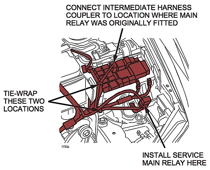
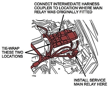
7. Disconnect the main relay from the fuse box, and install an intermediate harness between the fuse box and the main relay.
8. Tie-wrap the intermediate harness and emission harness together.
9. Tie-wrap the intermediate harness and B-terminal harness together.
10. Install the intermediate harness bracket at the bottom of the fuse box installed location. See Figure 1.
11. Reinstall the air cleaner.
12. Reconnect the air flow sensor connector.
13. (3.0L Engine Only): Reconnect the VAD three-way solenoid connector.
2003-05 Mazda6: Proceed to “Fuel Pump Relay Kit Installation Procedure” and install Fuel Pump Relay Kit.
2006-07 Mazda6: Proceed to the next step.
14. Reconnect the negative battery cable.
15. Re-enter the customer’s pre-seat radio stations.
2006-07 Mazda 6: Proceed to “Power Window Initialization Procedure” to restore “anti-pinch” and “auto open/close” window features before returning the vehicle to the customer.
Fuel Pump Relay Kit Installation Procedure (2003-05 Mazda6 Only)
1. Secure the intermediate harness bracket together with the PCM installation bracket.
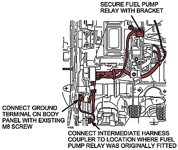
2. Tie-wrap the intermediate harness and harness together at three locations. Make sure the intermediate harness passes over the main relay bracket.
3. Disconnect the fuel pump relay from the relay box, and connect the intermediate harness to the fuel pump relay connector.
4. Connect the ground terminal on the body panel with the existing M8 screw. See Figure 2.
5. Reconnect the negative battery cable.
6. Re-enter the customer’s preset radio stations.
7. Verify the repair fixes the no-start.
Power Window Initialization Procedure (2006-07 Mazda6 Only)
1. Turn the ignition to the On position.
2. From the driver’s seat, ensure the window lockout switch is not depressed.
3. Press the window switch down to fully open the door window.
4. Pull the window switch up to fully close the door window; hold the switch up for two seconds; release the switch.
5. Move to the front passenger seat and repeat Steps 3 and 4 on the passenger window switch.
6. Verify the proper window operation using each door switch.