Instead of probing around in the dark it may be a good first step to look at the wiring diagram. Once you’ve isolated what system, or possibly even what circuit needs attention, the wiring diagram can help you make a better-educated guess before you start inflicting damage on the wiring harness of the vehicle.
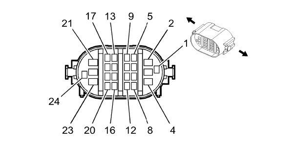
By using a wiring diagram, you can map the complete circuit from power to ground of the modules and actuators inbetween. Depending on the type wiring diagram, you can verify the circuit and its relationship with the connectors on the vehicle. If you use the connector “pinout” diagram, you can even see where a circuit is in the connector and avoid having to remove the electrical tape and corrugated sheathing going to a sensor, motor or another connector.
The other type of diagram that can help you is the ground distribution information. On most diagrams, the ground might just be the upside-down striped arrow indicating ground. Most modern vehicle wiring diagrams will include a code indicating the node or cluster of grounds connected to the body of the vehicle in a specific location, the information can typically be found on the ground distribution diagram. If you are dealing with a diagnostic dilemma involving multiple codes and symptoms on unrelated systems, it’s often a bad chassis ground used by the unrelated systems to blame.
By having the correct wiring diagram information before you start separating connectors and probing wires, you are avoiding the Heisenberg effect. Werner Heisenberg was an atomic physicist in the 1930s who came up with the uncertainty principle that says when you try to measure or observe something, you are changing how that object behaves. The same is true for electrical diagnostics: the second you start disconnecting connectors or flexing wiring harnesses, you could be causing new problems or even cause the problem you are trying to isolate to change how it acts.
Probing
The Hippocratic Oath states a doctor shall “do no harm.” The technician’s oath is the same, but we “do no harm” to a vehicle we are trying to diagnose or repair.
This oath has become more difficult to follow as vehicles have become more complex. Probably one of the most controversial topics among technicians is the probing and piercing of wires and connectors. Some technicians curse t-pins and piercing probes claiming they can damage a wiring harness.
Back in the day, a technician could carry out most electrical diagnostics with just a test light. Every voltage value was 12 volts, and the most sophisticated component was probably the ignition module. Things have changed. Modern voltages can be three-, five- or 12-volts and they might have a pulse. These signals move a ton of information. The flickering of a test light or dancing of digits on a multimeter could be serial data to command a window down or just a faulty ground. Also, even the slightest amount of green corrosion or high resistance can set codes.
Making the connection in the least invasive way possible is critical to achieving a confirmed diagnosis.
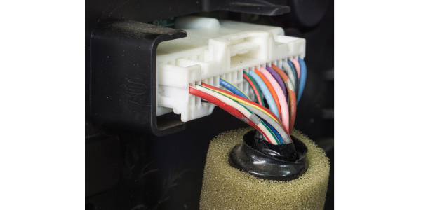
T-pins and needle probes have been around for a long time. These can be inserted into the back of a connector to back probe the connection. The best way to use these is to slide the pin between the connector housing and weather pack grommet. If there is no grommet, you can slide the pin gently into the insulation. There is no guarantee of contact between the pin and wire and there is no way to know if the pin is damaging the terminal. But, back probing with a pin might be your only option. Specialty back probes will have a small diameter and create less leverage on the connector. Some back probes have a rounded spade profile that can be used on small diameter wires.
One of the least invasive ways to connect to a circuit is a breakout. Some breakouts can be connector specific, like an oxygen sensor or OBDII connectors. Breakout test leads can mimic the male and female terminals in a connector.
Breakout leads can do the least amount of damage to the wiring and possibly the terminals, but they can also introduce a wild card into your diagnosis if you are not careful. In many cases, the connector is the source of an electrical problem. Disconnecting and reconnecting a connector might clear up a bad connection for a short time. This is why it is always a good idea to inspect both sides of the connector when you first pull it apart.
Even if a doctor saves a life, scars from a scalpel may be left behind. The sign of a good doctor is a less noticeable scar that heals. Wiring diagrams and the correct probes are ways technicians can avoid scarring a vehicle for life.