How can a mysterious case of tire wear occur in a perfectly aligned vehicle? It happens and the answers aren’t always simple. To better explain, let’s go back a few decades when I aligned a 1983 Mitsubishi rear-wheel drive (RWD) pickup, only to have it return a month later with a tire scuffing complaint. Although the outside edge of the right front tire showed evidence of toe-related wear, the current toe angle was 0.100 inches, which is within the Mitsubishi’s +0.080” to +0.350“ specification.
Perplexed, I decided to have my helper sit on the open tailgate. The toe angle immediately jumped from its original 0.100 inches to 0.500 inches. My conclusion was that many independent front suspensions often require a “custom alignment” to compensate for variations in ride height caused by uneven loading.
Toe Angle Defined
While, in theory, a rear axle’s thrust angle should align with the geometric centerline of the vehicle, it often doesn’t correctly align due to manufacturing errors and minor collision damage. With that said, individual wheel toe angle should be measured from the rear axle thrust angle rather than the geometric center.
Zero toe angle is present when both tires are parallel to the center thrustline. Positive toe is present when the front of both tires angle toward the thrust line, while negative toe is present when the front of both tires angle away from the thrust line. Total toe angle is the sum of the right- and left-hand toe angles. The toe angle on many older vehicles is displayed in fractions of an inch, whereas toe angle on later-model vehicles is displayed in degrees.
‘Bump’ Steering
Since many 4WD trucks are equipped with solid front axles, the toe angle won’t change with ride height. What does change is the horizontal angle of the drag link (which connects the tie rod to the steering gear) in relation to the front axle. When the drag link angle becomes too severe in relation to the solid front axle, a condition called “bump steer” exists, in which the front wheels actually change direction as the suspension is compressed or extended. In addition, the steering gear is forced off-center, which can aggravate steering wander.
Turning Radius
When the vehicle is driven around a corner, the inner wheel turns through a shorter radius than the outer wheel. To reduce tire scrub and improve steering response, the steering geometry forces the inner wheel to turn one or two degrees more than the outer wheel. This geometry forces total toe angle from a positive to a negative value. Turning radius is most affected by bent steering arms and knuckles. In any case, a bent steering arm or knuckle can cause tire scrub, even when the toe angle is aligned to specification in a straight-ahead position.
Independent Front Suspension
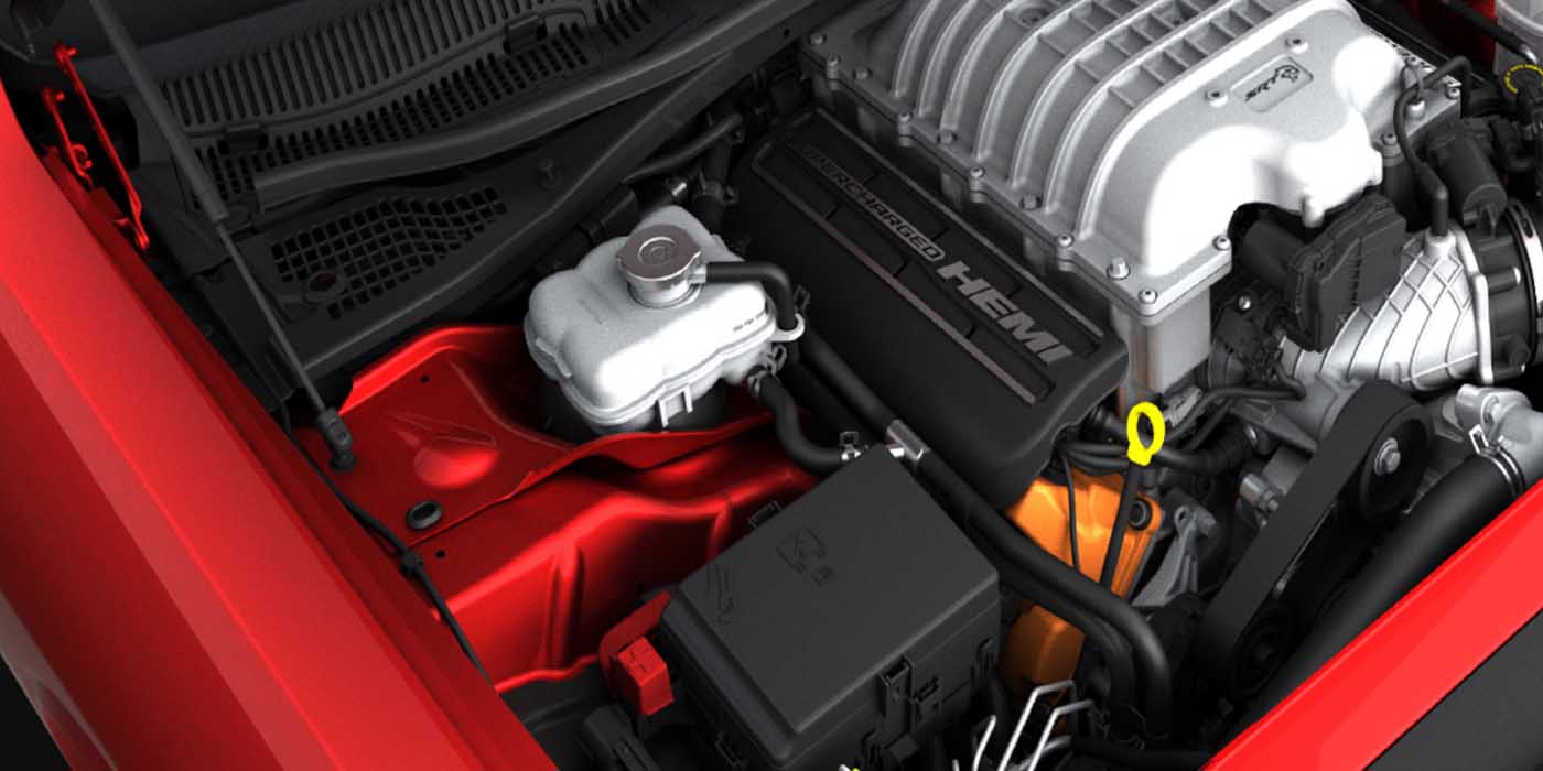
A bump steer phenomenon can occur with an independent front suspension. To illustrate, let’s look at the next two photos to analyze the effects of an increase in ride height on a typical SLA and MacPherson strut suspension system. See Photo 1 and Photo 2.
To analyze the effects of ride height on independent suspension geometry, increase the front ride height through one-inch increments when the vehicle is parked on your alignment machine. You should see a pronounced change, not only in toe angle, but in camber angle as well. Use the examples to visualize how alignment angles might change on SLA or MacPherson strut suspensions when ride height is increased or decreased. If the vehicle you’re aligning has a trailer hitch mounted, ask your customer how often he uses his trailer and how heavily it might be loaded.
Similarly, if the vehicle is a pickup truck, check for an uneven load distribution of tools and materials in the bed. If those tools or materials constitute a daily or average load, re-distribute that load and align the vehicle to specification. If the truck is carrying an unusually heavy load, the truck should be unloaded before aligning the front wheels. Whatever the situation, remember that you might have to increase or decrease the toe angle to reduce tire wear.
Analyzing Tire Wear
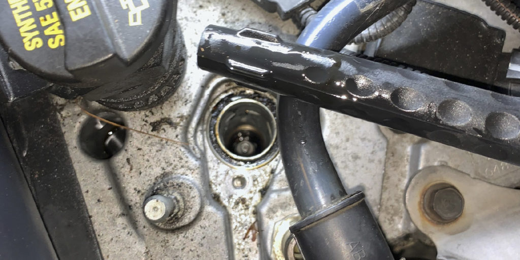
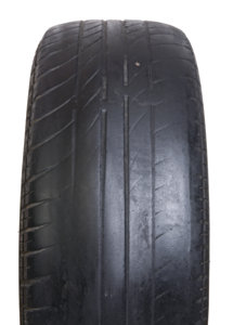
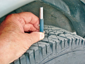
When analyzing tire wear, remember that modern tires have much more flexible sidewalls and more rigid tread belts. This makes them more tolerant of deviations from the “ideal” camber and toe angles. The most effective method I’ve found for analyzing tire wear is the simple process of checking tread depth across the tire tread. In many cases, a minor variation of 1/32” in tread depth can indicate the need for a slight change in toe angle. See Photo 3.
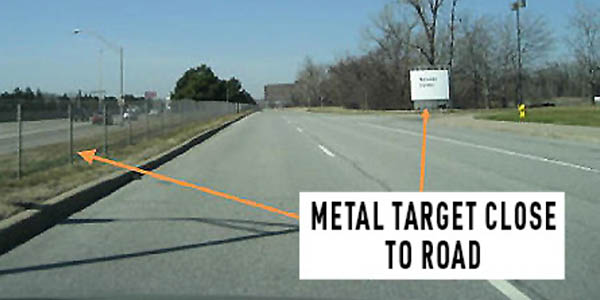
Road Crown Corrections
Remember that a driver steers toward the center of the road to correct for road crown. Excessive positive toe angle forces the passenger-side tire to “push” the car toward the center of the road. Excessive negative toe angle forces the driver’s-side tire to “drag” the car toward the center of the road. Therefore, if the wear is present on the outside edge of the passenger-side tire, the vehicle might be experiencing excessive positive toe angle.
If the wear is evident at the inside edge of the driver’s-side tire, the vehicle might be experiencing excessive negative toe. The severity of these wear patterns depends on the severity of the road crown and the condition of the suspension and steering linkage. Worn idler arms and tie rod ends will tend to aggravate the above wear patterns on vehicles with a parallelogram-type steering linkage.
To determine if a tire wear pattern is caused by positive or negative toe, stroke your fingertips across the tire tread. If the tread feels smooth going toward the tire’s inner edge and rough coming back to the outer edge, the vehicle might be experiencing excessive positive toe. The opposite effect will indicate excessive negative toe.
It’s also important to differentiate between toe and camber wear by remembering that positive or negative camber wear produces smooth tread wear in either direction. Remember that excessive wear in the upper or lower ball joints or pivot bushings will generally create excessive positive toe, whereas impact damage is more likely to cause excessive negative toe angle.
Basic Alignment Techniques
As always, the first step is to check for specified air pressure. Next, inspect the tires for uneven tread wear, sizing, tread pattern and circumference. Due to the requirements for anti-lock braking (ABS), vehicle stability control (VSC), and all-wheel drive (AWD), all four tires should vary no more than 1/4” in circumference and be of the same casing and tread design. Ball joint, tie rod, idler arm and suspension wear should also be checked. And since a suspension system can’t maintain alignment without good rebound control, don’t forget to also check the condition of the shock absorbers and struts.
My own technique for checking idler arm wear is to lift the right front wheel by the lower control arm and attempt to turn the wheel in and out by hand. An excessive change in toe angle and excessive vertical movement in the idler arm indicates excessive wear. With the alignment heads in place and wheel run-out corrected, record the current toe angle.
If it’s an RWD vehicle, hand-press between the fronts of the wheels to simulate tire rolling resistance and record that value. If it’s an AWD or FWD, hand-press at the rear of the front wheels to simulate forward drive thrust. In most cases, the toe angle should go to zero as the tires are hand-pressed. If the toe angle change exceeds specification, excessive cumulative wear is present in the steering linkage.
Next, I compare the tread wear pattern with the existing toe angle. If the tires are worn and the toe angle is correct, suspect an excessive change in ride height caused by unusual loading patterns. Check the toe angle by increasing the vehicle height in one-inch increments. If the toe angle coincides with the wear patterns mentioned above, you might be dealing with a loading problem rather than an alignment or wear issue.
Installing suspension and ride control components that are designed to increase the load-bearing capacity of the vehicle can minimize alignment problems that are caused by extreme variations in ride height. In addition, an incorrect camber or toe angle can often be remedied by adjusting torsion bar height.
Adjusting the toe angle to the maximum or minimum side of the specification can often reduce tire wear. In doing that, remember that too much negative toe angle will aggravate steering wander and that too much positive toe will reduce steering response. Within those windows of adjustment, adjusting a vehicle’s alignment specifications to meet real-world driving conditions can often reduce uneven tire wear complaints.