Wouldn’t it be great if various vibrations in the car were something that we could measure, sort through, select one, and assign numbers to it that can be used to find its source? Wouldn’t be even better if we could determine by the numbers whether the vibration was a balance issue or excessive runout with the component? Well, we can and by the end of this article you will see how it is done.
Understanding Vibrations
Imagine what often happens to a steering wheel during braking when the rotors are causing a brake pulsation. Imagine the steering wheel oscillating back and forth. An example of one complete cycle is when the wheel starts out center, moves to its farthest distance in one direction, passes center to the other direction, and then returns to center.
Hertz (Hz) is a measurement of how much of this cycle, or how many of these cycles occur over one second. 0.5Hz is 1/2 of the cycle over one second, 1 Hz is one complete cycle over one second, and 2 Hz is 2 cycles over one second and so on. 1 Hz is also equal to one revolution per second.
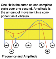 Everything on the vehicle has a preset frequency to it. A component’s frequency is determined by its size, mass, material composition, and is influenced by its speed of movement.
Amplitude is the amount of movement that has occurred with the component. The amplitude of the vibrating component is what the driver is feeling. Imagine listing to your radio in a noisy shop. If the volume is low, you may not hear it even though it is still producing sound. Once the volume is raised above the noise in the shop, then you can hear the radio. The concept is similar with the amplitude of vibrations. It isn’t until the amplitude is high enough that the driver can feel it that they complain about it.
Amplitude is expressed in G-forces on the electronic vibration analyzer. A tire that is vibrating at 0.03 Gs is just enough to lightly feel in the in the steering wheel. The vibrations produced by the average engine at idle are approximately 0.06 Gs when measured directly on the engine. At 0.08 Gs the vibration is hard enough to make loose change rattle in the cup holders.
When it comes to diagnosing and repairing a vibration, it is important to understand how the vibration travels through the vehicle. There is always an “originator,” a “conductor” and a “reactor.” The driver may be feeling a tire vibration in the seat, but it is obviously not the seat that is causing the vibration. The vibration is originating from the out-of-balance tires, traveling through the suspension and body, and then into the seat. So, in this example, the tires are the originator, the suspension and body are the conductor, and the seat is the reactor.
We, in theory, could fix this complaint by preventing the reactor from moving or changing the conductor so that the driver doesn’t feel the vibration. However, in this case, we would want to fix the originator of the problem by balancing or replacing the tires. Not all vibrations are fixed at the originator. In the case of a bad engine mount allowing the engine vibrations to enter the vehicle’s body, replacement of the conductor (the mount) is the fix. The mount is conducting too many normal engine vibrations into the vehicle’s body.
What about in the case of a heat shield on the exhaust that is loose and ratting? The heat shield is only reacting to vibrations that originated from the engine and traveled through the exhaust to the loose shield. The fix would be to tighten or replace the reactor (the heat shield).
 Order of Vibration
Vibrations are also expressed in “first order,” “second order” and so on. The “order” of the vibration is simply how many “bumps” it makes per revolution. Imagine a tire with one bubble in the tread. Every time that tire rotates, one “bump” can be felt as that one bubble slaps the road’s surface. That is a first order vibration. If there are two bubbles in a tire located in two different places, then two bumps can be felt per each revolution of that tire. That is a second order vibration. Three bubbles would make a 3rd order vibration, and so on.
It is important to remember that if a measurement and calculation is made that doesn’t exactly fit any component in the first order, it will be necessary to start looking at vibrations in the second order and on.
Engines have a preset order to their vibrations. That order is equal to half of the number of cylinders that an engine has. That is because per every one revolution of an engine, half of its cylinders fire producing a “bump” per firing. A four-cylinder engine has a 2nd order vibration, a six-cylinder engine has a 3rd order vibration, and so on.
 Vibration Measuring Tools
When it comes to vibration measuring tools, you certainly get what you pay for. The cheapest is called a Sirometer. A Sirometer is nothing more than a coil of wire inside of a two-piece plastic housing. Dialing the top half of the Sirometer lengthens and shortens the wire. The vibrations make the wire vibrate when the length is set just right for a particular frequency. Then the user reads a numeric scale on the housing of the Sirometer to see where a little pointer stopped at to get the frequency. Although it is surprisingly accurate, it is not made for automotive use where someone would be measuring frequencies while driving down the road. It is actually used by small engine technicians to determine engine RPM of lawnmower engines. The next slightly more expensive tool is a reed tachometer. A reed tachometer is a box with a set of reeds preset to vibrate at certain frequencies. This is better than the Sirometer because no adjusting is done to the tool. Simply look over at it to see the frequency. However, this tool was never made for automotive purposes either. It is commonly used to tune pianos. It will work, but the normal bumps on the road may produce inaccurate readings. Plus, neither the Sirometer or the reed tachometer will provide an amplitude reading. It is important to know the component’s amplitude when dealing with more than one vibration at the same time.
The tools of choice are electronic vibration analyzers (which are what you will see used in this article).The simplest versions provide Hz, RPM (Hz times 60), and amplitude. The most sophisticated of these tools go so far as to actually name the suspect part(s). When using the simpler versions of a vibration analyzer, is also wise to use a special vibration analysis software on your PC that performs the calculations for you and points directly to the suspect part(s).
 With any vibration measuring tool, always make your measurements under the conditions when the vibration is most noticeable. Then, always note the vehicle speed and engine RPM that correspond with the exact moment the vibration frequency is recorded. Plus, for best results make the measurements in places on the vehicle that the vibration can be felt the best at, like the seat tracks, steering column and floor pan. Taking measurements directly on the source of the vibration can result in inaccurate readings.
Classifying the Vibration
During the test drive, the vibration must be classified into whether it is vehicle speed related or engine speed related.
To determine if a vibration is vehicle or engine speed related, the easiest thing to do is slip the transmission into neutral and let the vehicle coast when the vibration is most noticeable. If the vibration continues, then the vibration is vehicle speed related. Likewise, if the vibration subsides, the vibration is engine speed related.
It’s imperative to know whether the vibration is vehicle or engine speed related so you know what parts to suspect.
 Calculating Natural Frequencies and Real World Testing
The vibration analyzer provides a frequency and amplitude of the component that is vibrating. As mentioned earlier, everything has a preset frequency that it omits when it vibrates. The frequency measured is a fingerprint of the component that is causing the problem. Just the same as a fingerprint can be used to identify a criminal, there must be something to compare it to in order to complete the identification process. This means we will have to calculate the frequencies of the spinning parts on the vehicle, then compare the measurements.
Let’s start with the tires. To calculate the frequency of a tire from scratch, first calculate the tire’s diameter. It is OK to use rounded numbers. For a 255/70R16 we will start by converting the width from metric to SAE by dividing 255 by 25.4. That gives us 10 inches. Then we will multiply the width in inches by the aspect ratio of 70%. That will look like 10 x .70 for a value of 7 inches. That is the height of the tire’s sidewall from the rim. But, that is only one side of the wheel. So, we will need to multiply that by 2 for a total of 14 to include both sides of the sidewall 360 degrees from each other. Then we will need to add back in the 16 inches of rim for a total diameter of 30 inches.
 To find the RPM of the tire, divide 20,850 by 30 for a rounded RPM reading of 695. Now that we have the RPM, we can determine the frequency, or revolutions per second, by dividing by 60 for an answer of 11.5 Hz. When using this formula, it will provide a Hz reading for vibrating tire at around 60 mph. The tire given here will produce a first order vibration between 11 Hz to 12 Hz reading if it were the source of the highway speed vibration. If there are two bubbles on the tire, then it will produce a second order vibration reading between 22 Hz and 24 Hz.
Now that we have the tire frequency, next we can calculate the drive shaft vibration for a rear-wheel-drive vehicle. First, obtain the rear axle ratio. Multiply the ratio by the first order tire frequency. The ratio will be 3.08. So, 3.08 x 11.5 Hz gives us 35.42 Hz. Therefore, at highway speed, an out-of-balance driveshaft on this vehicle will produce a reading between 35 Hz and 36 Hz at about 60 mph. If the driveshaft were bent in a way that produced a second order vibration, we would read between 70hz and 72hz. Remember though, this is for RWD drive shafts and not FWD half shafts.
A simple imbalance condition will always produce only a first order vibration. In order to have a second order or more vibration, something has to be bent or spinning off center. I’m sure you’re starting to see where this technology can be useful, let’s move on and see what this technology can really do.
 Let’s calculate engine frequency. As you can see, Hz is the same as revolutions per second. So, we have to divide the engine’s RPM by 60. Let’s say the vibration concern is at 2,500 RPM. It is determined that the vibration is the engine being felt in the body of the car. Is this a balance problem with the engine? Or is this a bad engine mount allowing normal engine vibrations into the vehicle’s body? We can tell the difference with a little math.
To find an engine’s first order vibration frequency, divide the 2,500 RPM by 60 for a frequency of 41.67 Hz. This frequency is the frequency of the engine spinning, or the crankshaft frequency. So, if there is a balance problem with the engine, such as slipped harmonic balancer or a thrown flex plate weight, the frequency of the vibration will be between 41 Hz to 42 Hz at 2,500 RPM. That is true regardless of the number of cylinders. However, if the vibrations felt are normal engine firing vibrations that are being transferred into the body of the vehicle, then the measurement is dependent on the number of cylinders that the engine has.
As we discussed earlier, engines have a preset order to their firing vibrations. For every one revolution, half of the cylinders “bump.” So, we take the crankshaft frequency and multiply that by half of however many cylinders an engine has. For a four cylinder, this is 2 x 41 equals 82 Hz of firing frequency at 2,500 RPM. A six cylinder is 3 x 41 for a firing frequency of 123 Hz. An eight cylinder is 4 x 41 equaling 164 Hz, and so on.
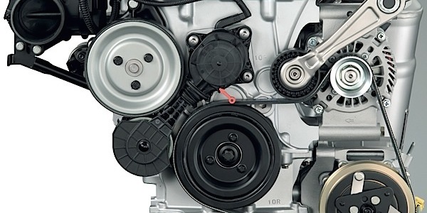
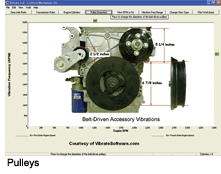
 So, let’s say you have a vehicle with a four-cylinder engine and an engine-related vibration felt in the driver’s seat of the car. If you measured 41 Hz at the driver’s seat track, you would know that you are looking for a balance problem with the engine. However, if you measured 82 Hz on that same vehicle, you know that you are likely dealing with a bad engine mount. OK, now let’s get serious. What if the vibration is caused by an accessory on the drive belt? Which one is it? Again, it’s all about the revolutions per second. So, we need to calculate the RPM of each component and convert that to RPS which is the same as the frequency. In order to determine the RPM of an accessory, we have to divide the crankshaft pulley diameter by the accessory pulley diameter (see photo Pulleys).
 Be sure not to measure diameter out at the outer lip. It must be measured down in where the belt rides. Then we multiply that value by the engine RPM, then divide that figure by 60. Let’s say we have a crank shaft diameter of 7 inches and an accessory pulley diameter of 3.5 inches. We would divide 7 by 3.5 for a value of 2 (the accessory pulley is spinning two times per every one crank pulley turn). We then multiply that “2” we got by the crank shaft RPM for an accessory RPM of 5,000 RPM. Then, to find the frequency we divide that 5,000 by 60 for a frequency of 83.3 Hz. So, if that particular accessory is causing the vibration, the measured frequency will be about 83 Hz at 2,500 engine RPM.
The Real World
Alright, let’s see what happens when classroom theory meets the real world. Let’s start simple and work our way up.
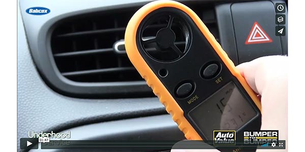
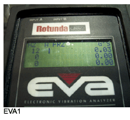
The first vehicle is an 2003 Taurus. It has P215/60/R16 tires. At 60 mph, a vibration can be felt. The vibration is vehicle speed related. It is felt in the seat and the steering wheel. The old “buttometer” says it is a common tire balance problem. The EVA shows 12 Hz and .03 G at the vehicle speed of 60 mph (vehicle speed tracked on a scan tool). See photo EVA1.
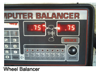
The calculated frequency of these tires, and everything spinning at that same speed as the tires, is 13 Hz. The rotors, tires, hubs and the half shafts are suspected. One of the tires was found to be 5 oz out of balance (see photo Wheel Balancer).
 The balance fixed the problem, but what if it didn’t? What if the tires were in perfect balance and not out of round? Then at least we would know for sure that we are looking for something that can create a 12 Hz first order vibration at 60 mph. We also know for sure that it has to be something that is turning at same speed as the tires since those items are the only thing turning that slow. This helps narrow our search.
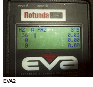
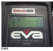
What if we measured 36 Hz? What could make a 36 Hz vehicle speed related vibration that might be similar to tires? 36 Hz doesn’t match anything in the first order or the second order for that car, but it does match the tripod joint on a CV axle when looked at in the 3rd order. The next vehicle is an 2001 Silverado 2×4. This truck has a vibration around 40 mph and 1,500 RPM that is hardly noticeable, but is there. The vibration analyzer has picked up a vibration of 36 Hz measured at the center console (see photo EVA2).
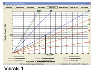
The rear differential ratio is 3.73 and the tires are 255/70R16. Everything is found earlier in this article for you to calculate the source of the vibration. However, let’s try some special software the does the calculations for us. After plugging the rear differential specs into the software, and the engine RPM at which it occurred, we get an answer of first order drive shaft vibration. (see graph Vibrate1)
The vibration is labeled as a first order propeller shaft vibration. And what do you know, the software and manual calculations are correct.
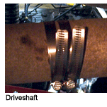
Hose clamps were added to the drive shaft to generate this vibration (see photo Driveshaft1). For this last vibration test, we have an 2001 Silverado with an engine vibration most prominent at 2,000 RPM. The vibration can be heavily felt in the steering wheel. At 2,000 RPM and sitting still, the vibration is measured in the steering wheel. 42 Hz is measured (see photo EV3).
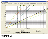
All of the pulley diameters were measured and data was entered. The crank pulley is 7.5 inches in diameter, 6 inches for the water pump, 2.25 inches for the alternator and 3.5 inches for the idler. The power steering is 6.35 inches and the tensioner pulley is 3.0 inches. The formula to manually calculate this has been covered earlier in the article. Using the software, the water pump is quickly labeled as the trouble maker (see graph Vibrate2).
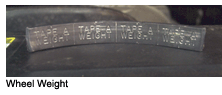
Sure enough, it was the water pump pulley that I hid this wheel weight in (see photo Wheel Weight).
Obviously, this is not technology that you would take the time to use on every tire vibration that rolls through the door. However, I’m sure you can see where this technology can be very useful when a tire balance doesn’t fix the problem or the vibration is otherwise unusual. Special thanks to VibrateSoftware.com for permission to use data captures and a picture of pulleys from their software.