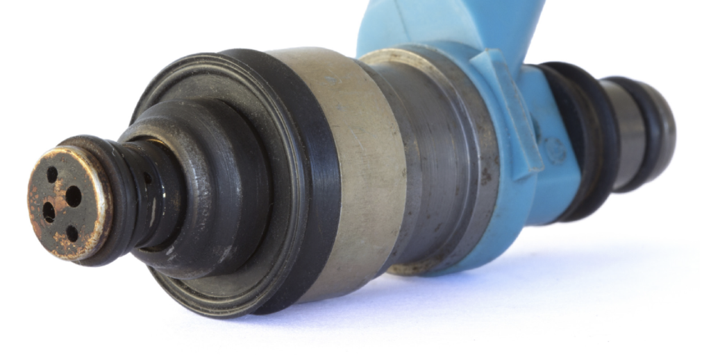
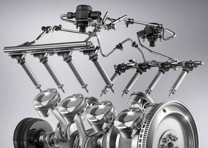
No matter if it is a high-pressure direct fuel injector or a port fuel injector, both operate the same way. The injector is a valve that opens and closes at precise intervals. On one side of the injector is pressurized fuel; on the other is a nozzle aimed at the combustion chamber.
On the majority of injectors, an electromagnetic coil is energized by a driver in the engine control module. As the coil is saturated by energy, the pintle moves upwards against a spring, allowing fuel to be injected into the engine.
The latest direct-fuel injection piezoelectric fuel injectors work in the same manner, but instead of a spring, the movement of the pintle is controlled with piezo discs arrayed in a stack around the pintle. These discs change in shape when electricity is applied. Since the pintle movement is not dependent on a copper coil becoming saturated with electricity, the amount of fuel delivered is more precise.
Voltage
Most injectors use 12 volts to energize the coil, and the driver energizes the circuit by pulling it to ground. When the injector is energized, the voltage drops to almost zero. If it does not, it could mean an open or weak connection in the wiring harness or open coils inside the injector.
When the voltage is turned off, the needle starts to close. When it closes, it generates a voltage spike known as the inductive kick. This is a generated magnetic field collapsing in the coils. This spike can range from 50 to 100 volts (at low current). Some circuits use a diode to cap the voltages seen at the driver to prevent damage. These diodes will dump the voltage to ground if they reach a specific range. This may cause the peak to be cut off on the waveform.
On the backside of the inductive kick, you may see a small positive hump or bump. This is the pintle hitting the seat of the injector and closing. This is a very powerful diagnostic insight.
Do not backprobe piezoelectric injectors. The voltages can range from 60-130 volts. You can damage some scopes with these high voltages. The best way to diagnose is with a current clamp.
Current
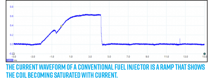
The current waveform of a fuel injector is a ramp that shows the coil becoming saturated with current. The current ramp starts to go up as soon as the voltage is applied by the driver. The ramp can be split into two parts.
The first part is where the injector is closed while the coil has yet to build up enough electromotive force needed to counteract the spring on the back of the pintle.
When there is enough current in the coil, the needle moves. This event can be seen as a small rise in the slope. Where it appears in the slope is debatable. Many variables like injector specifications, fuel pressure and other factors can change the position of the event on the waveform. However, some scopes might not be fast enough to catch it.
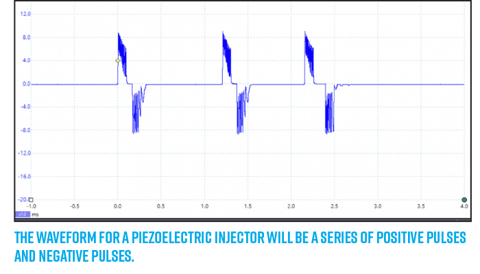
Piezoelectric injectors have a different type of waveform. When voltage is applied to the stack of crystals, they change shape so the pintle can move. The polarity is then changed, the stack changes back to the original shape and the pintle closes.
The waveform for a piezoelectric injector will be a series of positive pulses and negative pulses. One side opens the injector the other closes the injector. The length and number of pulses depend on how much fuel the engine needs. It is difficult to make a generalization about piezoelectric waveforms. The best advice is to find a “known good” waveform and OE service information.
Diagnostics
Diagnosing a saturated switch fuel injection circuit with a scope can help you to confirm the health of the drivers and injectors. You can compare the waveforms to other injectors on the vehicle or to a known-good waveform found online or in the service information. On their own, the current and voltage waveforms can confirm that the internals of the injector are moving. This can be very helpful when trying to track down a misfire problem due to an open, leaking or stuck injector.