“CAN” is the new buzz word in automobile diagnostics. It stands for Controller Area Network and is a protocol for onboard diagnostics and scan tools. CAN is a high-speed data link that provides more information at a faster rate for better communication between onboard electronics and external diagnostic equipment. Many manufacturers have already started incorporating the technology in their 2003-’04 models, and by 2008, all diagnostic communications are to be done by CAN communications.
ur shop services Mercedes-Benz vehicles, and we’re already seeing cars with failing CAN communications. Mercedes started using CAN communications between controllers with the chassis 140 “S” class in 1992.
Running a “short test” has been a required component of all vehicle servicing for years on Mercedes vehicles. Many cars haven’t had this service performed, and doing the test on a car that hasn’t had its codes routinely evaluated and cleared will many times give five to six pages of codes. Cars with these lists of codes most likely won’t have any warning lights on, and the systems will still be functioning. The codes are just a record of momentary problems created for many reasons.
High on these lists of codes are those for lack of CAN communications between various controllers. When these codes are just stored codes and aren’t current, they are usually a result of control units that are affected by voltage problems like low batteries. If a number of these codes are set in different modules with no symptoms and are not currently existing, I usually suspect the battery.
CAN Networks
Mercedes-Benz has a number of networks on its current lineup of cars. These networks have different characteristics. CAN C is the chassis or powertrain buss. It carries communications between engine management, transmission and traction control modules in all models with a varying amount of more specific modules on later cars. Such modules include the electronic shift module, active suspension, distronic (radar-based cruise control) and headlight range-adjusting modules. The CAN C is the faster, wired communicating network on the vehicle, with communication speeds up to 500 kbps.
The other hard-wired network for most models is the Body CAN or CAN B. It communicates at 83 kbps and ties the many other simple-function body modules together. There can be 10 to more than 30 of these modules connected to the CAN B, depending on the model. There are a number of modules that talk to CAN C and CAN B, such as the instrument cluster and the steering column module. These modules pull inputs or command activity from both networks, but do not transfer data. In all cars up to 2002, the EIS (electronic ignition switch) is the only module that passes data or commands from one CAN to the other. After 2002, a new module called a central gateway module handles the link-up and the new diagnostics via CAN D.
For years I had been real happy to not have problems with these communications systems. The communications protocols and just the concept seemed so much more difficult than normal automotive electronics. After working through a number of CAN problems, I find that their diagnostics is usually straightforward, especially with the help of the onboard diagnostics of modern scanners.
CAN Quandaries
The CAN networks can cause a number of problems, which I group into three general categories. The most obvious are control units that don’t function, eliminating the ability to adjust seats, windows, locks, etc. “Limp home” conditions are another obvious problem on the CAN C – transmissions that don’t shift and engine speed limitations associated with throttle position uncertainty and/or traction control doubts. The third general category, and maybe the most allusive, is the gradual battery drain and dead batteries due to the CAN B not going to sleep. As long as any controller continues sending communication, the whole body CAN stays active and the control units stay switched on. This can result in current drains near 1,000 ma. The EIS not only is the gateway between networks, but is also in control of activation and deactivation of the CAN B. The CAN B network has numerous systems that are operable without the key being on and as such requires such communications without the ignition key turned on, leaving the possibility of extensive current drain.
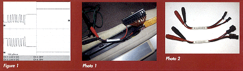
When determining the source of current drain with the key off, a good first step is to determine whether the CAN B is in its proper sleep mode. One telltale sign is whether the mileage indication in the instrument cluster is on. A more accurate mechanism is to read the sleep state of the CAN B low and high circuits. Early cars (202, 208 and 210 chassis) are dormant when the low signal is 4.8V and the high signal is 0.025V. The active voltages for low have the signal drop from 3.2V and the high signal goes high from 1.8V (see Figure 1). Note that the zero of channels 1 and 2 are separated, as if placed together the actual signals would overlap. The pattern was clipped and assembled from a 30-second snapshot where the car was allowed to go to sleep. The time frame is so small that the actual moment wasn’t captured. The pattern is assembled from a before-and-after image. The pattern was captured by accessing the X30/7 connector bussbar in the passenger-side door sill (see Photo 1).
On models starting with 220, the dormant low line is battery voltage, or 11V, and the high line is dormant at 0.025V, similar to early cars. The active voltage is: low 4.65V, high 0.65V. In all cases, the data on each line goes low from the active voltage for CAN L and goes high from the active voltage for CAN H.
These voltages (shown in Figure 1) represent characteristics of the network and are best viewed at the X connectors. The X connector, labeled voltage distributors, is basically a buss bar. The numerous modules are attached to this buss. The amount of “X” buss connectors varies by model and their location and distribution characteristics should be the first step in observing the system.
A pair of breakout leads offered by Mercedes-Benz (P/N 220 589 00 99 30 for CAN B busses and P/N 220 589 99 31 for CAN C applications) allows a single controller leg to be “broke out,” leaving the controller engaged, but allowing the voltages for CAN H and L to be read, and allowing for ohm readings between the two sides and between each side and ground to check for open and shorted network wiring. See Photo 2.
Shorted or open signals can make the whole CAN instable. CAN C for drivetrain will run with one side disabled, but it has been my experience that one side down on CAN B will stop all controller functions.
CAN Diagnostics in Action
A common CAN B problem I have seen twice, and read about in tech groups a couple of times, provides a good example of how simple and methodical diagnostics can be. The first time I saw it was on a 1999 E430 (210 chassis). The customer complained that the windows, seats, locks, sunroof, steering wheel and a couple other systems were all inoperative.
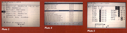
I started diagnostics at the activation screen of the EIS module (see Photo 3). Next, I entered EIS (see Photo 4). The EIS is the place to diagnose all CAN B networks through 2002. In “Activations” the status of the CAN is given and an inventory of modules communicating are listed (see Photo 5). In this case, the status was “instable” and none of the modules were online. I then checked the wiring diagram in WIS at PE00.19-P-2300-99EA. The EIS is hooked to the SAM (driver’s side signals acquisition module) by a twisted pair of brown and brown with red striped wires. The SAM is connected to the X30/7 buss bar with a brown and brown with black stripe twisted pair. There are eight other modules in this case and they are all hooked to the X30/7 with brown and brown with red twisted pairs. Note: The SAM pair can be seen in the middle of the X30/7 in Photo 1.
The SAM connection is thus easy to identify and disconnecting it brought the CAN status back to stable. Of course, all the modules were now disconnected and still offline.
At this point all the twisted pairs were pulled from the X30/7 connection and reconnected one at a time until the system went instable again. That connection was left off and all the rest, when connected, left the CAN stable. Checking the module status chart showed the right rear door control module offline. Replacing the door control module repaired the car.
The “X” Files The early cars – 202, 208 and 210 – have only one “X” connector buss. Later cars – 203, 215 and 220 – have at least three “X” busses. The diagnostics are similar. Look at the distribution of modules on a wiring diagram. Look at the stability of the CAN B system on the scanner under Activation of EIS. Separate the “X” busses at their coupling connections until the scanner shows the network go stable. Then dissect the pertinent “X” buss until the defect is removed.
A similar diagnostic dissection can be used to find the controller or input to a controller that is keeping the CAN B awake. Install the breakout connector and monitor the awake/sleep voltage on the network. It should drop to sleep voltage within two minutes of all doors being closed. If the voltage doesn’t drop, disconnect the links between the “X” busses until it does. Once it’s sleeping, add the “X” busses or modules until it is no longer sleeping. A quick look at the block diagram of the central locking system shows the numerous modules that receive inputs for the system. The door switches are monitored by the rear SAM. The IR sensors talk to the door control modules and the motion and glass breakage are often monitored by the OCP (overhead control panel).
The powertrain network CAN C probably has the most responsibility as it is involved constantly with the basic functions of driving: the engine, transmission and braking (including traction control and stability). It also can be diagnosed from guided tests in EIS. Testing in this case is similar to a short test: the pertinent modules are queried and they report their status. Faults will be recorded in each module or they won’t reply.
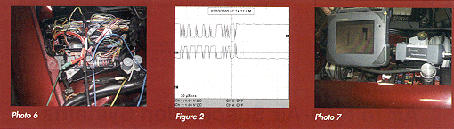
The network itself is best diagnosed as a simple two-wire system. The wires run in parallel to each controller, not touching each other or the chassis. As in an SCSI PC network, this system does connect the two network cables with terminating resistors. These are both 120 ohms. This then becomes two 120 ohm resistors in parallel, which measured anywhere on the system should show 60 ohms. (An easy point of observance is gained using the breakout lead attached to the ESP controller on this 210 chassis car. See Photo 6.)
This is the most significant of tests as it basically verifies the integrity of the network. In most systems, the terminating resistors are inside the ME controller and the EIS. In MLs without EIS, the terminating resistor moves to the instrument cluster. If the system shows resistance different from 60 ohms, it must be separated and evaluated. A reading of 120 ohms means an open in one leg CAN L or CAN H. A reading of less than 60 ohms means there is a resistance in one of the modules or a bridge between the two systems. Other than the terminating controllers, the controllers should have 10-50 kohms resistance internally. A look at the signal on CAN C (Figure 2) doesn’t really show much for diagnostics, but it is an example of the voltage when active and the speed of the signal. In this case, the scope is maxed out timewise and the signal is obviously faster than the view taken. Note: The scanner images were taken using an SDS BASIC on a 2001 E320. All 210 chassis cars must be diagnosed through the 38-pin connector, which is in the engine fuse panel (see Photo 7).
Steve Brotherton is co-owner of Continental Imports, a 22-bay shop in Gainesville, FL, that employs 18 people, 10 of whom are technicians. Brotherton has been an ASE-certified Master Technician since 1973 and is a recertified L1 specialist. In addition, he is a Bosch Certified Master Tech.