Leave your wrenches in your toolbox because in this month’s Diagnostic Solutions, we’re going to explore how to diagnose many common powertrain control module (PCM)-related driveability and electrical problems by following what I call The Electronic Trail. Last month, I recorded a complete “movie” of the on-board electronic functions or “electronic trail” of a 2005 Honda Element that I was diagnosing for a no-cranking condition (see last month’s article). Since I kept that data in my scan tool library, I’ll use it as a working example for this month’s discussion of scan tool procedures. I’ll also be using a current model of a popular aftermarket scan tool to illustrate my diagnostic process.
THE BATTERY
Electronic trails always begin with the battery. In this case, I didn’t see a voltage drop on my scan tool as I engaged the starter, which told me that the starter was open-circuit, probably at the brushes. Key-off, engine-off, a fully-charged battery should maintain at least 12.4 volts across its terminals, with 12.6 volts indicating full charge on a wet-cell battery. Higher voltages are considered “surface charges,” that can be eliminated by turning on exterior lighting for a few minutes. Voltages in the range of 9.5 volts or less indicate a bad battery cell or a discharged condition.
SAVING DATA
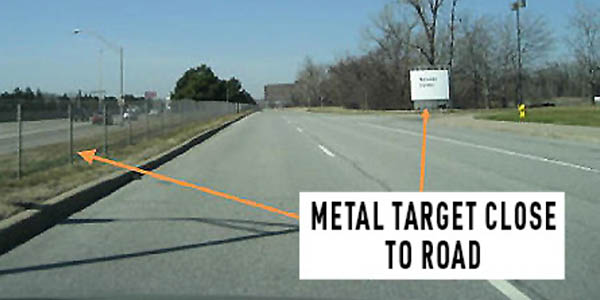
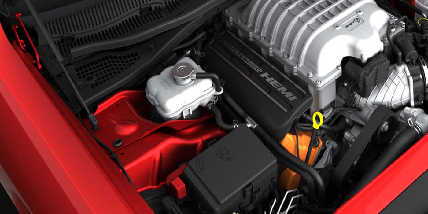
The next step on the Electronic Trail is to immediately record DTCs and parameter indicator data (PIDs) either in your scan tool’s memory or on a notepad. Too many times, I’ve had DTCs disappear after one ignition on/off cycle. To be completely accurate, when battery voltage drops to 12.0 volts, the battery is considered completely discharged. While the battery might have enough volts and amps to power the instrument cluster, DTCS stored in the PCM will usually be erased when the starter engages. If you are in doubt about battery voltage and condition, connect a jumper battery to maintain battery voltage before attempting to retrieve DTCs from the PCM. See Photo 1 and Photo 2.
Electronic trails often display a pattern of DTCs shared among modules. While modern vehicle systems automatically poll all modules for DTCs, it’s important to manually retrieve that information by communicating with all modules on models that don’t have automatic polling.
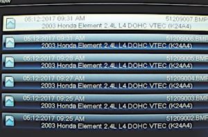
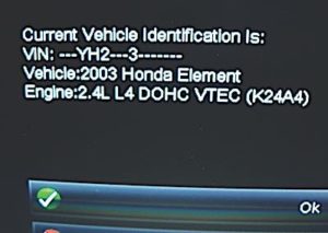
As VIN information is entered or automatically displayed on the scan tool, use the “save” button to record that information as well for future reference. As DTCs are retrieved from the various modules, record them in your scan tool’s memory in order of their appearance for future reference.
As a sidelight, I save the VIN programmed into the PCM and compare it with the VIN located on the vehicle’s door jamb and windshield areas. Just a few years ago, I ran into a problem diagnosing a cranking, no-start condition on a vehicle with a freshly remanufactured, but incorrectly programmed PCM.
While code terminology and protocol vary widely among manufacturers, most DTCs will fall under the general definitions of “current,” “history,” or “pending.” Current codes are those that are generally considered to be “hard” codes that can be easily duplicated. In contrast, history codes are those that have been stored in the PCM’s diagnostic memory, but might not be “active” or “current.”
Pending codes are often “two-trip” codes that have met their enabling criteria for setting the code, but have not yet met the “trip” criteria for turning on the malfunction indicator light (MIL).
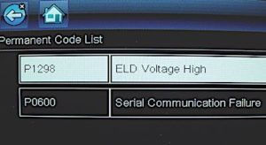
Our Honda Element labels “history codes” as a “Permanent Code List.” Honda’s “temporary” (pending) list shows “No Codes Present.”
Notes From the Electronic Trail
1. The most famous last words of diagnostics are, “I KNOW what the problem is (without even looking)!” Remember that problems can’t be solved with a closed mind.
2. On an industry note, dealership and independent diagnostic technicians usually live in different worlds. At one end of the diagnostic universe, dealership techs diagnose a limited number of new and late-model platforms, typically with one or more DTCs. At the other end of the diagnostic spectrum, independent technicians often must diagnose platforms with multiple DTCs and an average age of 11+ years with multiple components in various stages of wear and degradation. Not that the independent sector has it too hard. Remember that dealership technicians live and die by the factory flat-rate manual while aftermarket technicians are free, or should be free, to set their own times and rates.
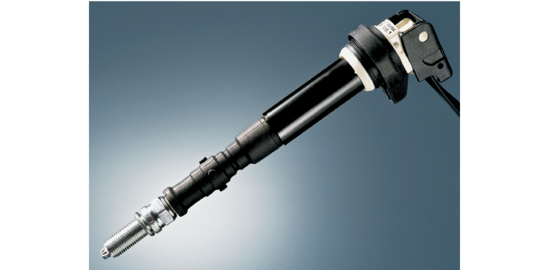
3. On the technical side, an accurate diagnosis depends upon much more than a scan tool’s condensed code description (see Photo 4). To accurately determine why and how a DTC is stored, a diagnostic tech must consult the enabling criteria needed to create and set the diagnostic code. It’s also important to understand that some original equipment manufacturers (OEMs) require special tools like an OEM harness break-out box to measure volts, amps and ohms in various circuits. In many cases, the aftermarket diagnostic tech is forced to design a work-around method for accomplishing the same objective.
4. Last, and certainly not least, it’s time we understand that “symptom diagnostics” is obsolete in the modern import shop. The “symptom” that we’re seeing might actually be an operating strategy used by software engineers to compensate for a mechanical or electronic failure. While modern on-board diagnostics are becoming far more comprehensive than in the past, they’re also far more complex to understand when they fail, which makes it more important than ever to understand how various operating systems actually work in today’s modern import car.
DATA ANALYSIS
Since I captured a movie of the Honda Element’s data stream, let’s analyze some important PIDs. The “RPM” PID indicates the presence of crankshaft position (CKP) sensor input to the PCM. Zero rpm displayed during a cranking, no-start condition normally indicates a lack of a CKP signal. Remember that a CKP signal is required before ignition, fuel pump or fuel injection activity can take place. “MAIN RELAY ON” indicates that the fuel pump is activated.
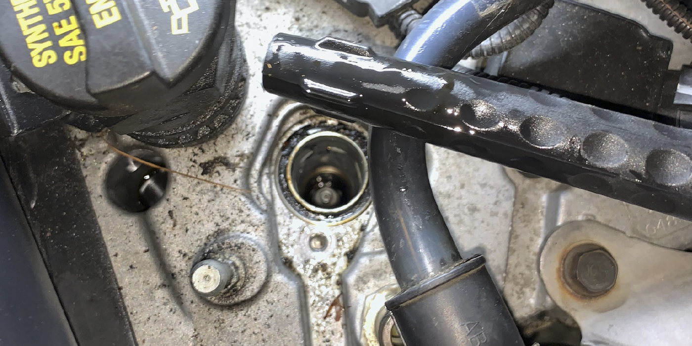
To diagnose rich/lean fuel conditions, observe the engine running in closed loop. The “AF FB AVG” PID indicates a perfect air/fuel ratio or “Lambda.” The “AF Sensor (mA)” PID indicates zero amperage flowing to or from the AFR sensor, which also indicates that the air/fuel ratio (AFR) sensor is at Lambda. See Photo 3.
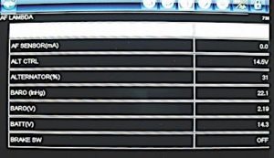
Charging system diagnostics are simple when using an enhanced scan tool. The “Alt Control” PID indicates 14.5 alternator charging volts, which is normal on a cool morning for Honda’s Electronic Load Detection (ELD) charging system. The “Alternator%” PID tells us that the alternator is charging at a 34% duty cycle, or 1/3 of its operating capacity to re-charge a partially discharged battery.
The alternator’s higher-than-average duty cycle tells me that the Honda’s new battery had been partially discharged overnight. Regarding a potential cranking, no-start condition, the “Immobilizer” PID is indicating “RUN.” If the Honda’s immobilizer is activated, the PID will indicate “BAN,” which indicates that the fuel system has been disabled.
VERIFYING DATA
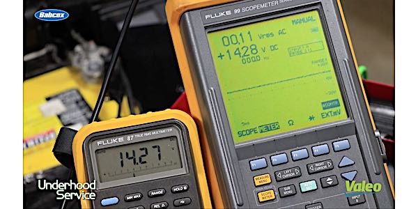
I always look at the following PIDs because they can be verified by test equipment. The “BARO (inHg)” sensor PID, for example, indicates barometric pressure or altitude. In this case, 22.1” Hg translates to about 8,000 feet altitude on a stormy day, which is correct information. If the Baro PID indicated 18.1” Hg, I’d suspect a bad baro sensor or PCM. If the baro data is calculated rather than direct-reading, the mass air flow (MAF) sensor should be inspected and tested.
The “BATT (V) PID indicates 14.3 battery volts, which can be verified with a common voltmeter at the battery. Here again, if the actual voltage value significantly differs from the scan data (ex. 14.3 volts and 12.8 volts), the wiring could have a voltage drop or the PCM might have a data processing problem. Any major differences between the direct and indicated voltage values can be evidence of a bad PCM.
While I didn’t get into some of Honda’s more esoteric data acronyms, most of Honda’s common PCM-related data are recognizable, which makes Following The Electronic Trail in pursuit of a no-cranking, no-start complaint a much easier task.