Courtesy Porsche Cars North America, Inc.
When moisture enters the Porsche Stability Management contact plugs in the main harness, it may activate the PSM warning light in instrument cluster on 2003 Cayenne, Cayenne S and Cayenne Turbo models.
You will need the following parts to repair the main wiring harness: P/N 955.612.918.00 New/repair kit (only if necessary); P/N 955.612.917.00 New/groundlead (only if necessary).
You will also need the following tools to carry out the repair. Repair kit for wiring harnesses (Cayenne); Press-out tool set (Cayenne) No. 155-3; Press-out tool No. 1591; and PIWIS tester.
REPAIRING THE MAIN WIRING HARNESS
Disconnect the battery ground terminal.
Remove the cover for the cowl panel according to the Workshop Manual, Group 6, Chapter 66 44 19.
Remove the DME control module according to the Workshop Manual, Group 2, Chapter 24 70 19.
Repair the main wiring harness according to the Workshop Manual, Group 9, Chapter 97 09 41.
Install the DME control module according to the Workshop Manual, Group 2, Chapter 24 70 19.
Install the cover for the cowl panel according to the Workshop Manual, Group 6, Chapter 66 44 19.
Connect the battery ground terminal.
Carry out the work instructions after disconnecting the battery as listed in the Workshop Manual, Group 9.
Preliminary Work:
Disconnect the battery. See 90 Work instructions after disconnecting the battery.
Remove the cowl panel cover. See 664419, Removing and installing cowl panel cover, chapter on “removing.”
Remove the DME control module. See 247019, Removing and installing DME control module, chapter on “Removing.”
Removing Support For DME Control Module:
Screw down the fastening nut (see Fig. 1, 1) and take off the ground strap with the twist lock.
Open the retaining clips (see Fig. 2, arrow A, on page 48) and take out the DME control module wire harness (arrow B).
Unscrew the fastening screw (see Fig. 2, 2) and the two fastening nuts (see Fig. 2, 3), and take out the support for the DME control module.
REMOVING THE INTAKE PIPE ON THE HEATING/FRESH AIR UNIT
Pull out the wire harness retaining clips on the intake manifold (see Fig. 3, arrow A ) and unclip the wire harness on the intake manifold (see Fig. 3, arrow B).
Pull out the air inlet grille (see Fig. 3, arrow C).
Open both retaining clips in the intake manifold (see Fig. 3, arrow D).
Unscrew the two fastening nuts (see Fig. 3, 1) and remove the intake manifold.
Repair Main Wire Harness (PSM Connector):
Warning: There is a risk of damage to the electrical wiring and malfunction of the brake system. The work procedure shown may only be performed by an “experienced” skilled worker.
Release the Porsche Stability Management control unit connector (see Fig. 4, arrow a) and pull it off.
Note: The following three repair versions for the PSM control unit connector can be selected. The repair version depends on the extent of the damage (the number of the corroded contacts).
If only the two contacts of the ground straps are corroded, the ground straps must be replaced.
If, in addition to the ground straps, approximately one half of the remaining contacts are corroded, the ground straps and the affected contacts must be replaced.
If, in addition to the ground straps, more than one half of the remaining contacts are corroded, the complete connector for the PSM control unit with the ground straps must be replaced.
For all three repair variations, the contacts on the PSM control unit must be examined carefully for traces of corrosion. If existing traces of corrosion cannot be removed, the hydraulic unit must be replaced. (See 453019, Removing and installing hydraulic unit.)
Note: For these repairs, use the prescribed repair kit from the Porsche Spare parts catalog, 9/20/10 (PET).
Repair kit ground straps for hydraulic unit.
Repair kit wiring harness subpart for hydraulic unit.
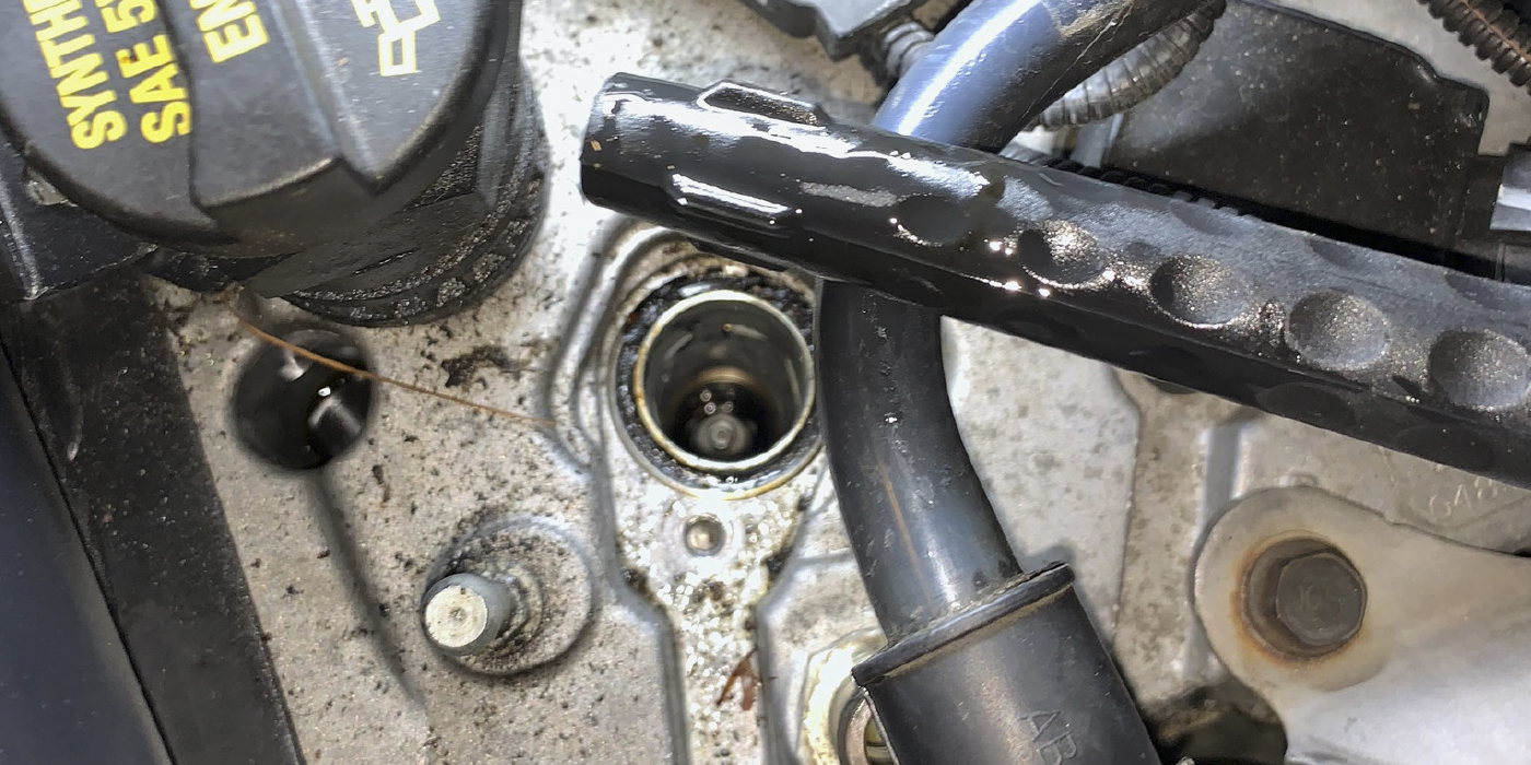
Examine the contacts in the PSM control unit connector for traces of corrosion and check all seals and lines for processing faults. Check the connector for damage/deformation; if in doubt, replace it (see Fig. 5).
Release the retaining clips (see Fig. 6, arrow a) and slide off the hood wire harness plug connection (see Fig. 6, arrow B).
Release the hood wire harness plug connection (see Fig. 6, arrow a) and disconnect it (see Fig. 6, arrow C).
Screw down the fastening nut (see Fig. 7, 1 on page 50) and take off the ground strap with the twist lock.
Pull out the wire harness (see Fig. 8, 1 on page 50) under the hydraulic unit. Remove the armouring and disconnect the ground strap from the hood wire harness.
Open the three retaining clips (see Fig. 9, arrow B) and take out the wire harness.
Expose the wire harness from the PSM control unit connector up to the foam grommet (see Fig. 9, 1) in the firewall. To do this, remove the corrugating hoses and the armouring.
Release the cap on the PSM control unit connector four times (see Fig. 10, arrows a) and take it off.
Remove the tie-wrap (see Fig. 10, 1) on the PSM control unit connector.
Open the secondary locking on the PSM control unit connector.
Note: If necessary, mark the electric lines. For allocation, see the wiring diagram (depending on the model year).
Press the contacts for the ground strap (see Fig. 11, 2), using the pressing-out tool (1591), and the remaining corroded contacts (see Fig. 11, 1), using the pressing-out tool (1556-2P) from the pressing-out tool set for Cayenne, NR.155-3, out of the PSM control unit connector.
Check the contacts using good lighting, with the aid of magnifying glass if necessary, to find traces of corrosion. Contacts having uniformly light and shiny surfaces are acceptable.
Completely remove the corroded ground straps (see Fig. 11, 2) from the wire harness.
Cut off, strip and check any remaining corroded lines (see Fig. 11, 1) for traces of corrosion. Shorten the original line from the vehicle electrical system until bare copper without signs of corrosion appears in the crimping area. The line length should be sufficient in order to position the crimping on the firewall in the area above the foam grommet.
Note: The electric lines are located in the plenum panel and are thus exposed to the highest demands. The procedure for stripping insulation from, crimping and shrinking/insulating the electric lines must be complied with and observed. The procedures are described in detail in the repair kit for harnesses, NR.1561. Crimping samples should be prepared before beginning work.
Crimp the crimping sleeve (see Fig. 12, 3) using the hand crimping pliers from the repair kit for harnesses (NR.155-1) to the original line from the vehicle electrical system (see Fig. 12, 2).
Push the shrink-fit hose (see Fig. 12, 4) onto the new line (see Fig. 12, 1).
Crimp the crimping sleeve (see Fig. 12, 3) using the hand crimping pliers from the repair kit for harnesses (NR.1 55-1) to the new line (see Fig. 12, 1). Check the crimp connection carefully.
Slide the shrink-fit hose (see Fig. 12, 4) over the crimp connection and carefully shrink it using the hot-air blower with a special nozzle (recommended accessories for the repair kit for harnesses) so that it is watertight.
Slide the new line (see Fig. 12, 1) into the PSM control unit connector until the contact is felt to engage.
Slide the new ground straps (see Fig. 13, 1) from the repair kit into the PSM control unit connector until the contacts are felt to engage.
Close the secondary locking on the PSM control unit connector (see Fig. 14).
Tie together the wire harness with insulating tape and route it so that the crimps (see Fig. 15, 1) can be positioned on the firewall in the area above the foam grommet (see Fig. 15, 2) in stages.
Attach a new tie-wrap (see Fig. 16, 1) to the PSM control unit connector.
Mount the cap on the PSM control unit connector until it is felt to engage (see Fig. 16).
Attach the armouring to the wire harness from PSM control unit connector up to the foam grommet (see Fig. 17, 1 on page 54) in the firewall and fit corrugating hoses.
Mount the PSM control unit connector and lock (see Fig. 17, arrow A).
Insert the wire harness in the three retaining clips and close them (see Fig. 17, arrow B).
Route the wire harness (see Fig. 18, 1) under the hydraulic unit.
Mount the ground strap, together with the twist lock on the stud and screw, down with the fastening nut. Fastening the nut for securing the ground strap to the body, M6 Position. Tightening torque: 6.5 ft.-lb.
Push the plug connection for the hood wire harness together (see Fig. 19, arrow A) until it is felt to engage.
Push the plug connection for the hood wire harness onto the retaining clips (see Fig. 19, arrow B) until it is felt to engage.
INSTALLING THE INTAKE PIPE
Position the intake manifold and secure it with both fastening nuts. Fastening nut to secure intake manifold to body, M6 Position. Tightening torque: 4.5 ft.-lb.
Close both retaining clips in the intake manifold.
Insert the air inlet grille.
Clip in the wire harness to the intake manifold and insert the wire harness retaining clips on the intake manifold.
Installing Support For DME Control Module:
Position support for the DME control module and screw down both fastening nuts (see Fig. 20, 3) and the fastening screw (see Fig. 20, 2). Fastening nut for securing support for DME control module to body, M6 Position (see Fig. 20, 3). Tightening torque: 6 ft.-lb. Fastening nut for securing support for DME control module to body, M6 Position (see Fig. 20, 2). Tightening torque: 6 ft.-lb.
Insert the DME control module in the retaining clips (see Fig. 20, arrow A) and close the retaining clips (see Fig. 20, arrow B).
Mount the ground straps, together with the twist lock on the stud and screw, down with the fastening nut. Fastening nut for securing ground strap to body, M6 Position. Tightening torque: 6.5 ft.-lb.
SUBSEQUENT WORK
Install the DME control module. See 247019, Removing and installing DME control module, chapter on “Removing.”
Install the cowl panel cover. See 664419, Removing and installing cowl panel cover, chapter on “Installing.”
Connect the battery and carry out the work instructions after disconnecting the battery. See 90, Work instructions after disconnecting the battery.