A long time ago, I learned a method of splicing wire that has stuck with me since those early days. I actually picked this method up while I was in the military (USMC), so I can’t take credit for inventing it or perfecting it.
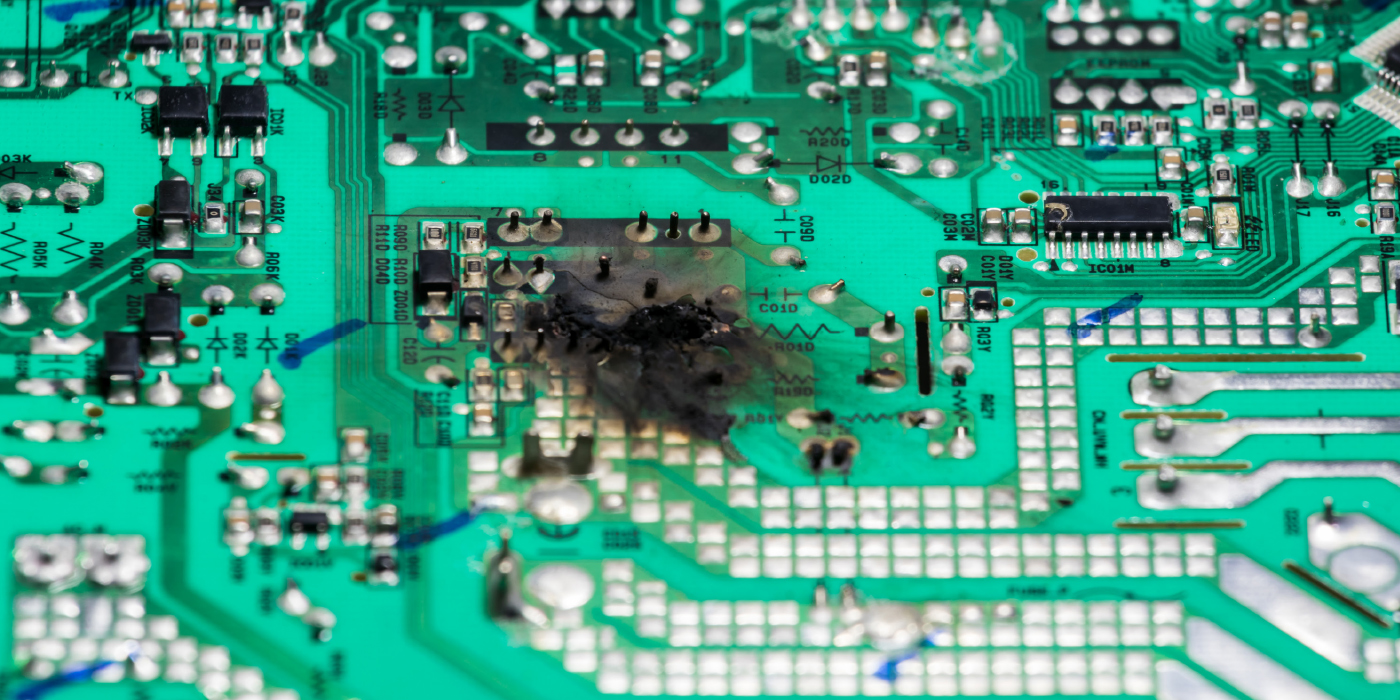
The resistance from a weak connection or poor connection can produce a tremendous amount of centralized heat. This heat can build the longer the current is flowing, which also increases the resistance even more.
Electricity does not flow “in” the wire, it actually travels “on” the surface of the wire. This is one of the many reasons why there are so many small strands in a given wire. A butt connector is one surface area, the surface area of the strands in a wire are not entirely used. The strands in the middle of the wire are trapped between the other strands and have no chance to pass their electrical effort. This forces the current to travel only through those strands that are actually touching the surface of the butt connector. The fewer wire strands being used, results in more heat buildup.
Using this hand splice method will allow a great deal more strands from each wire section to be touching the spliced area as possible.
First thing to do is strip back about 3/4 of an inch of insulation from both wires that you’re going to be splicing. Add a section of shrink tubing onto the wire. (Don’t forget this step… or you’ll regret it after you’ve finished the splice.)
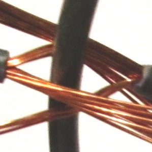
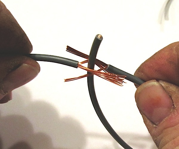
Divide the bare strands into two equal sections and form them into a “Y.”
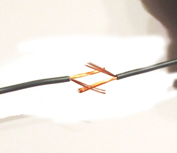
Hold a wire in each hand, now take the “Y” and interlock the two wires together. But, (very important) leave room between the two “Y”’s large enough for the outer insulation from the “none” strip section of wire to easily pass through. Lay the “Y” sections down along the wire without bending them backwards, straight and even with the wire.
Find the edge of the gap you left in the “Y”’s (That thickness measurement of the outside insulation, just about halfway between the two wires).
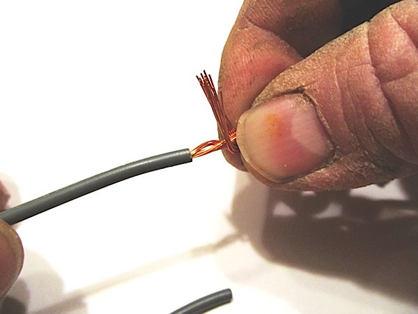
Using one hand, pinch down on that spot while taking the legs of the “Y” from the same side and stand them straight up 90 degrees from the splice. Now, using your other hand, with firm finger pressure rotate the two legs of the “Y” around the splice towards the opposite wire. If done correctly, the spacing you left between the two “Y”s will actually lie down and end up right where the insulation begins. Also, as you pinch and roll the bare wire, keep it snug as possible. You want to end up with it no larger than the outside diameter of the insulated sections.
Now switch procedures from the right hand to the left hand and stand the other set of “Y” legs 90 degrees and do the same crimp and turn all the way to the other insulated section of wire.
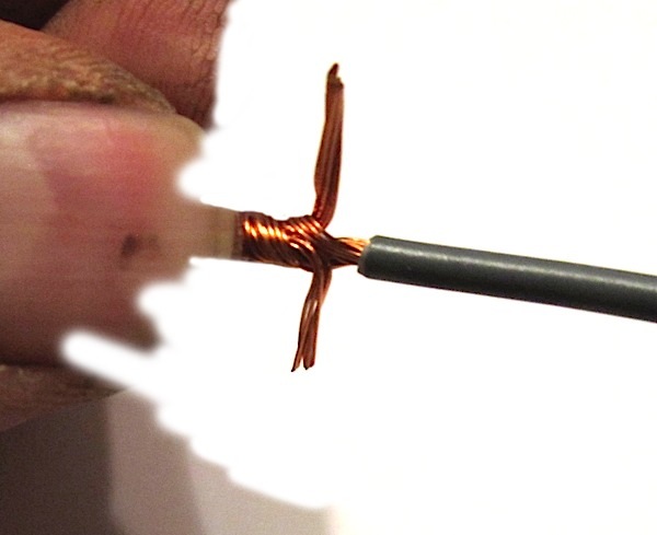
Once you’ve got the hang of it, you’ll find that the splice is extremely strong even without solder or shrink tubing.
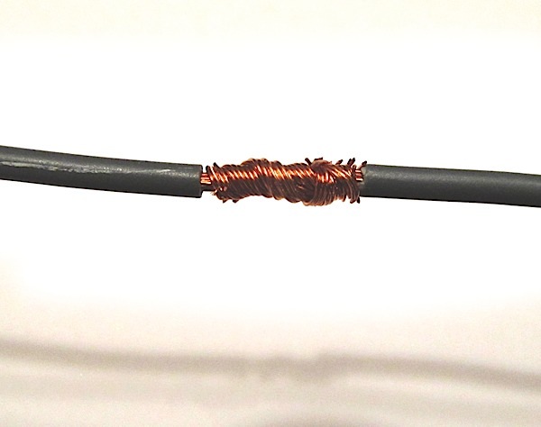
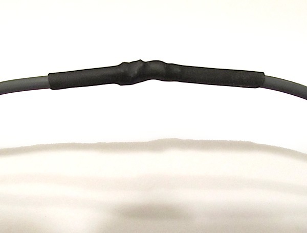
When soldering, be sure not to soak the splice with solder. The solder is only to aide in holding the splice in place so it won’t unravel. Obviously the shrink tubing is for overall weather protection, and to shield the bare wire.
Done right, the splice should have plenty of mechanical hold without soldering. I don’t recommend this for battery cable (4 gauge and larger).
Crimp or soldered connectors are still the best method for them. But for the average gauge wire, this method works extremely well.
Give it a try, and when you’ve mastered the technique, try it on your friends and see how much effort it takes them to pull it apart, even without soldering it.